Figure 3-2. board setup diagram -3 – Cirrus Logic CRD49530-USB User Manual
Page 22
3-3
Copyright 2008 Cirrus Logic
DS705RD3
Installation, Setup, and Running First Application
CRD49530-USB User’s Manual
•
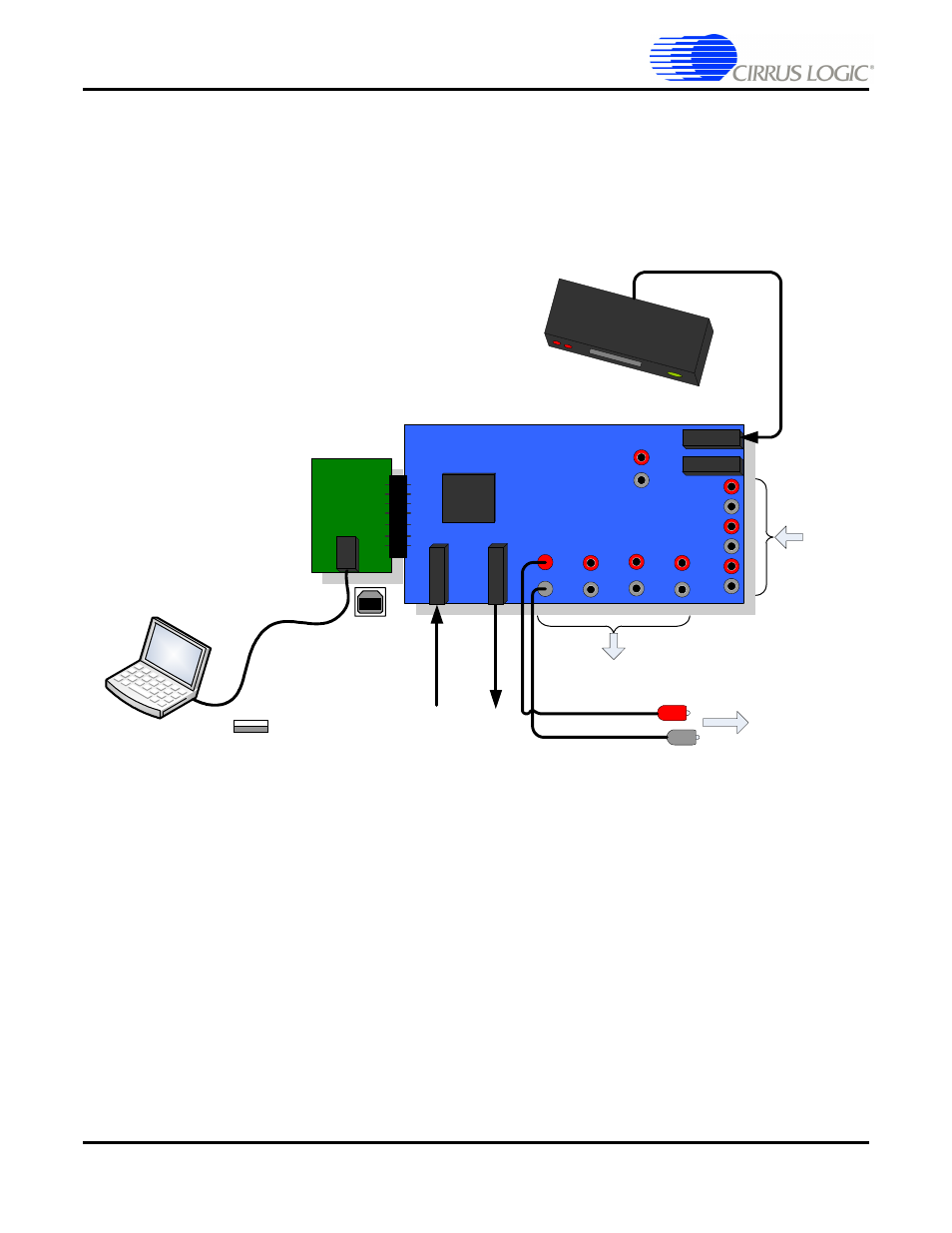
Connect the other end of the optical cable to the optical output on the back of a DVD player or other
digital audio source.
6. Make Audio Output connections from the CRD49530 board.
•
The RCA connectors labeled AOUT1 and AOUT2 are the left and right analog output channels.
•
Use the RCA audio cables to connect these line-level analog outputs to powered speakers.
Figure 3-2. Board Setup Diagram
SPDIF_RX0
CS4953x
U
S
B
SPDIF_RX1
L
R
Ls
Rs
C
Sub
USB
Cable
Power
Cable
RCA Cables
To Powered
Speakers
DVD P
layer
Optical
Cable
Analog
Inputs
SPDIF_RX2
SPDIF_RX3
Optical
Output
Optical Output on
DVD Player
Cirr
us L
ogic
So
ftw
are
USB 2.0
Port
S
P
D
IF_
TX
PW
R
“A”
“B”
Analog
Outputs
L
R
Ls
Rs
C
Sub
SbL
SbR
- CobraNet (147 pages)
- CS4961xx (54 pages)
- CS150x (8 pages)
- CS1501 (16 pages)
- CS1601 (2 pages)
- CS1601 (16 pages)
- CS1610 (16 pages)
- CRD1610-8W (24 pages)
- CRD1611-8W (25 pages)
- CDB1610-8W (21 pages)
- CS1610A (18 pages)
- CDB1611-8W (21 pages)
- CDB1610A-8W (21 pages)
- CDB1611A-8W (21 pages)
- CRD1610A-8W (24 pages)
- CRD1611A-8W (25 pages)
- CS1615 (16 pages)
- AN403 (15 pages)
- AN401 (14 pages)
- AN400 (15 pages)
- AN375 (27 pages)
- AN376 (9 pages)
- CRD1615-8W (22 pages)
- CRD1616-8W (23 pages)
- AN402 (14 pages)
- AN404 (15 pages)
- CRD1615A-8W (21 pages)
- CS1615A (16 pages)
- CS1630 (56 pages)
- AN374 (35 pages)
- AN368 (80 pages)
- CRD1630-10W (24 pages)
- CRD1631-10W (25 pages)
- CS1680 (16 pages)
- AN405 (13 pages)
- AN379 (31 pages)
- CRD1680-7W (31 pages)
- AN335 (10 pages)
- AN334 (6 pages)
- AN312 (14 pages)
- AN Integrating CobraNet into Audio Products (16 pages)
- CobraNet Audio Routing Primer (9 pages)
- Bundle Assignments in CobraNet Systems (3 pages)
- CS2300-01 (3 pages)
- CS2000-CP (38 pages)