Chapter 2: introduction to crd49530-usb kit, Figure 2-1. crd49530-usb system block diagram -1, Pc xe m3001 – Cirrus Logic CRD49530-USB User Manual
Page 16
2-1
Copyright 2008 Cirrus Logic
DS705RD3
Introducing the CRD49530-USB Customer Reference Kit
CRD49530--USB User’s Manual
Chapter 2
Introduction to CRD49530-USB Kit
2.1 Introducing the CRD49530-USB Customer Reference Kit
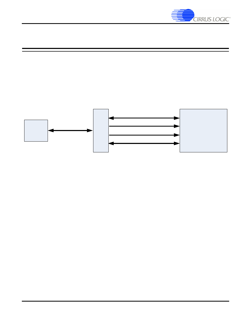
The CRD49530-USB kit is composed of the CRD49530 customer reference design and the CRD USB
Master USB Control board. The CRD49530 provides a practical platform for emulating a typical multi-
channel audio system application. The CRD USB Master is a USB control board used to interface the host
PC to the CRD49530, and convert GUI commands into the serial control protocol required for configuring
the CS4953xx, CS42448, and CS8416 audio ICs.
shows the relationship between the
CRD49530 and the CRD USB Master.
Figure 2-1. CRD49530-USB System Block Diagram
This document will concentrate on the features and basic operation of the CRD49530 board. Detailed
information regarding the operation and programming of the CS4953xx DSP is covered by the CS4953xx
Data Sheet, CS4953xx Hardware User’s Manual, and application note AN288 (see
for more details).
The CRD49530 is a convenient and easy-to-operate evaluation platform. It has been designed to
demonstrate the majority of the CS4953xx functions on a small 6" x 5.5" base board. These features
include:
•
PC control of the CS4953xx using the DSP Composer
™
graphical user interface
•
Serial control of audio devices on CRD49530 via I
2
C
®
or SPI™ protocols
•
Digital audio input of PCM or compressed data via optical or coaxial S/PDIF
•
6-channel analog audio input via the CS42448 audio codec
•
8-channel analog output through the CS42448 audio codec
•
Digital audio output of PCM data via optical S/PDIF
•
Multi-channel digital audio input via the USB Master (feature not currently supported)
•
Separate input and output clocking domains to allow 1FS-to-2FS audio processing on the CS4953xx
•
DSP Memory expansion through external 64 Mbit SDRAM
•
Fast boot – host-controlled master boot (HCMB) of custom applications from 4 Mbit serial SPI flash
device.
•
Microphone input with integrated amplifier for Intelligent Room Calibration (IRC) evaluation
•
Supports all members of the CS4953xx and CS497xx family in the 144-pin LQFP package.
CRD49530
Reset Signals
USB Port
Serial Control Interface
Board Control Signals
Audio Data (Future Development)
PC
XE
M3001