Cirrus Logic CS4341A User Manual
Features, Description, 101 db dynamic range
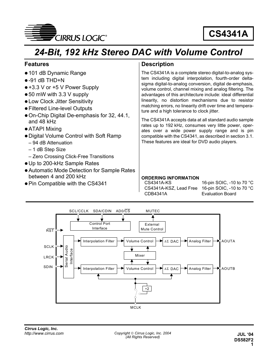
Table of contents
Document Outline
- CS4341A
- 1. PIN DESCRIPTION
- 2. Typical Connection Diagram
- 3. Applications
- 3.1 Upgrading from the CS4341 to the CS4341A
- 3.2 Sample Rate Range/Operational Mode Detect
- 3.3 System Clocking
- 3.4 Digital Interface Format
- 3.5 De-Emphasis Control
- 3.6 Recommended Power-up Sequence
- 3.7 Popguard® Transient Control
- 3.8 Grounding and Power Supply Arrangements
- 3.9 Control Port Interface
- 3.10 Memory Address Pointer (MAP)
- 4. Register qUICK rEFERENCE
- 5. Register Description
- 6. Characteristics and Specifications
- Specified Operating Conditions
- Absolute Maximum Ratings
- ANALOG CHARACTERISTICS (CS4341A-kS)
- combined interpolation & on-chip analog Filter response
- Figure 10. Single-Speed Stopband Rejection
- Figure 11. Single-Speed Transition Band
- Figure 12. Single-Speed Transition Band (Detail)
- Figure 13. Single-Speed Passband Ripple
- Figure 14. Double-Speed Stopband Rejection
- Figure 15. Double-Speed Transition Band
- Figure 16. Double-Speed Transition Band (Detail)
- Figure 17. Double-Speed Passband Ripple
- SWITCHING SPECIFICATIONS - SERIAL AUDIO INTERFACE
- SWITCHING specifications - CONTROL PORT interface
- SWITCHING specifications - CONTROL PORT INTERFACE
- dC Electrical characteristics
- DIGITAL Input characteristics
- DIGITAL InTERFACE specifications
- 7. PARAMETER DEFINITIONS
- 8. References
- 9. PACKAGE DIMENSIONS