7 reset line, 8 error reporting and interrupt behavior, Cs4244 – Cirrus Logic CS4244 User Manual
Page 42
DS900F1
42
CS4244
When the upper “x” bits, as dictated by the DAC1-4 NG[2:0] settings, are either all “1’s” or all “0’s” for 8192
consecutive samples, the Noise Gate will engage for that channel. Setting these bits to ‘111’ will disable
the Noise Gate feature. If the Noise Gate feature engages, it will transition into and out of mute as dictated
by the
bit in the
.
4.7
Reset Line
The reset line of the CS4244 is used to place the device into a reset condition. In this condition, all of the
values of the CS4244 control port are set to their default values. This mode of operation is the lowest power
mode of operation for the CS4244 and should be used whenever the device is not operating in order to save
power. During the power up and power down sequence, it is often necessary for the CS4244 devices to be
placed into (and taken out of) reset at a different moment in time than the amplifiers to which they are con-
nected in order to minimize audible clicks and pops during the sequence. For this reason, it is advisable to
run separate reset lines for each type of device, i.e. one reset line for the CS4244 devices and one for the
amplifier devices.
4.8
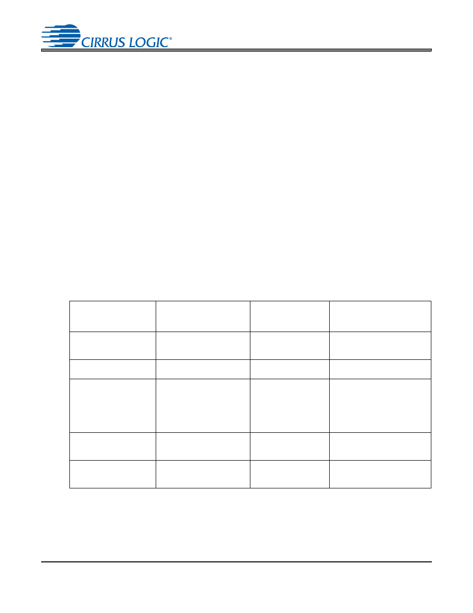
Error Reporting and Interrupt Behavior
The CS4244 is equipped with a suite of error reporting and protection. The types of errors that are detected,
the notification method for these errors, and the steps needed to clear the errors are detailed in
It is important to note that the interrupt notification bits for all of the errors are triggered on the edge of the
occurrence of the event. They are not level-triggered and therefore do not indicate the presence of an error
in real time. This means that, a “1” in the error’s respective field inside the Interrupt Notification register only
indicates that the error has occurred since the last time the register was cleared and not necessarily that
the error is currently occurring.
Table 8. Error Reporting and Interrupt Behavior Details
Note:
35. This error is provided to aid in trouble shooting during software development. Entry into the test mode
of the device may cause permanent damage to the device and should not be done intentionally.
Name of Error
Event(s) that
Caused the Error
Outputs Muted
Upon Occurrence?
All PDNx bits must be set
and then cleared to
resume normal operation?
Disallowed Test Mode
Entry
Device has entered test
mode due to an errant I²C
write.
No
No
Serial Port Error
FS/LRCK, or SCLK has
become invalid.
Yes
Yes
Clocking Error
The speed mode which the
device is receiving is different
than the speed mode set in
the
bits, or
the PLL is unlocked from
input signal.
Yes
Yes
ADCx Overflow
ADC inputs are larger than
the permitted full scale signal.
No
No
(Normal operation will continue
but audible distortion will occur.)
DACx Clip
DAC output level is larger
than the available rail voltage.
No
No
Normal operation will continue
but audible distortion will occur.