2 left justified and i·s modes, Cs4244, 2 left justified and i²s modes – Cirrus Logic CS4244 User Manual
Page 30
DS900F1
30
CS4244
4.5.2
Left Justified and I²S Modes
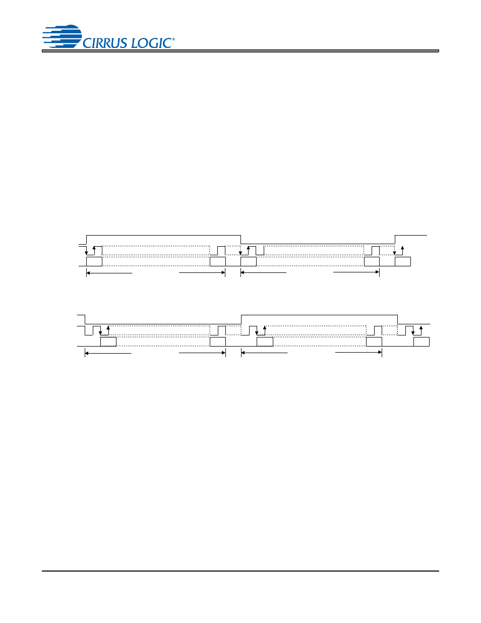
The serial port of the CS4244 supports the Left Justified and I²S interface formats with valid bit depths of
16, 18, 20, or 24 bits for the SDOUTx pins and 24 bits for the SDINx pins. All data is valid on the rising
edge of SCLK. Data is clocked out of the ADC on the falling edge of SCLK and clocked into the DAC on
the rising edge. In Master Mode each slot is 32 bits wide.
) the data is received or transmitted most significant bit (MSB) first,
on the first rising edge of the SCLK occurring after a FS/LRCK edge. The left channel is received or trans-
mitted while FS/LRCK is logic high.
) the data is received or transmitted most significant bit (MSB) first, on the sec-
ond rising edge of the SCLK occurring after a FS/LRCK edge. The left channel is received or transmitted
while FS/LRCK is logic low.
The AIN1 and AIN2 signals are transmitted on the SDOUT1 pin; the AIN3 and AIN4 signals are transmit-
ted on the SDOUT2 pin. The data on the SDIN1 pin is routed to AOUT1 and AOUT2; the data on the
SDIN2 pin is routed to AOUT3 and AOUT4.
FS/LRCK
SCLK
M S B
L S B
M S B
L S B
AOUT 1 or 3
L e ft C h a n n e l
R ig h t C h a n n e l
SDOUTx
SDINx
AOUT 2 or 4
MSB
AIN 1 or 3
AIN 2 or 4
Figure 17. Left Justified Format
FS/LRCK
SCLK
M SB
L S B
M S B
L S B
AOUT 1 or 3
L e ft C h a n n e l
R ig h t C h a n n e l
SDOUTx
SDINx
AOUT 2 or 4
MSB
AIN 1 or 3
AIN 2 or 4
Figure 18. I²S Format