2 power-down, 3 dac dc loading, Section 4.2.3 – Cirrus Logic CS4244 User Manual
Page 23: Figure 9, For the cs4244 reset is, Cs4244
DS900F1
23
CS4244
4.2.2
Power-down
To prevent audio transients at power-down, the DC-blocking capacitors must fully discharge before turn-
ing off the power. In order to do this in a controlled manner, it is recommended that all the converters be
muted to start the sequence. Next, set PDNx for all converters to 1 to power them down internally. Then,
FS/LRCK and SCLK can be removed if desired. Finally, the
must be set to ‘1’ for a period of 50 ms before applying reset or removing power or MCLK. During this
time, voltage on VQ and the audio outputs discharge gradually to GND. If power is removed before this
50 ms time period has passed, a transient will occur and a slight click or pop may be heard. There is no
minimum time for a power cycle. Power may be re-applied at any time.
It is important to note that all clocks should be applied and removed in the order specified in
MCLK is removed or applied before
RST
has been pulled low, audible pops, clicks and/or distortion can
result. If either SCLK or FS/LRCK is removed or applied before all PDNx bits are set to 1, audible pops,
clicks and/or distortion can result.
Note:
Timings are approximate and based upon the nominal value of the passive components specified in the
“Typical Connection Diagram” on page 7
for volume ramp behavior.
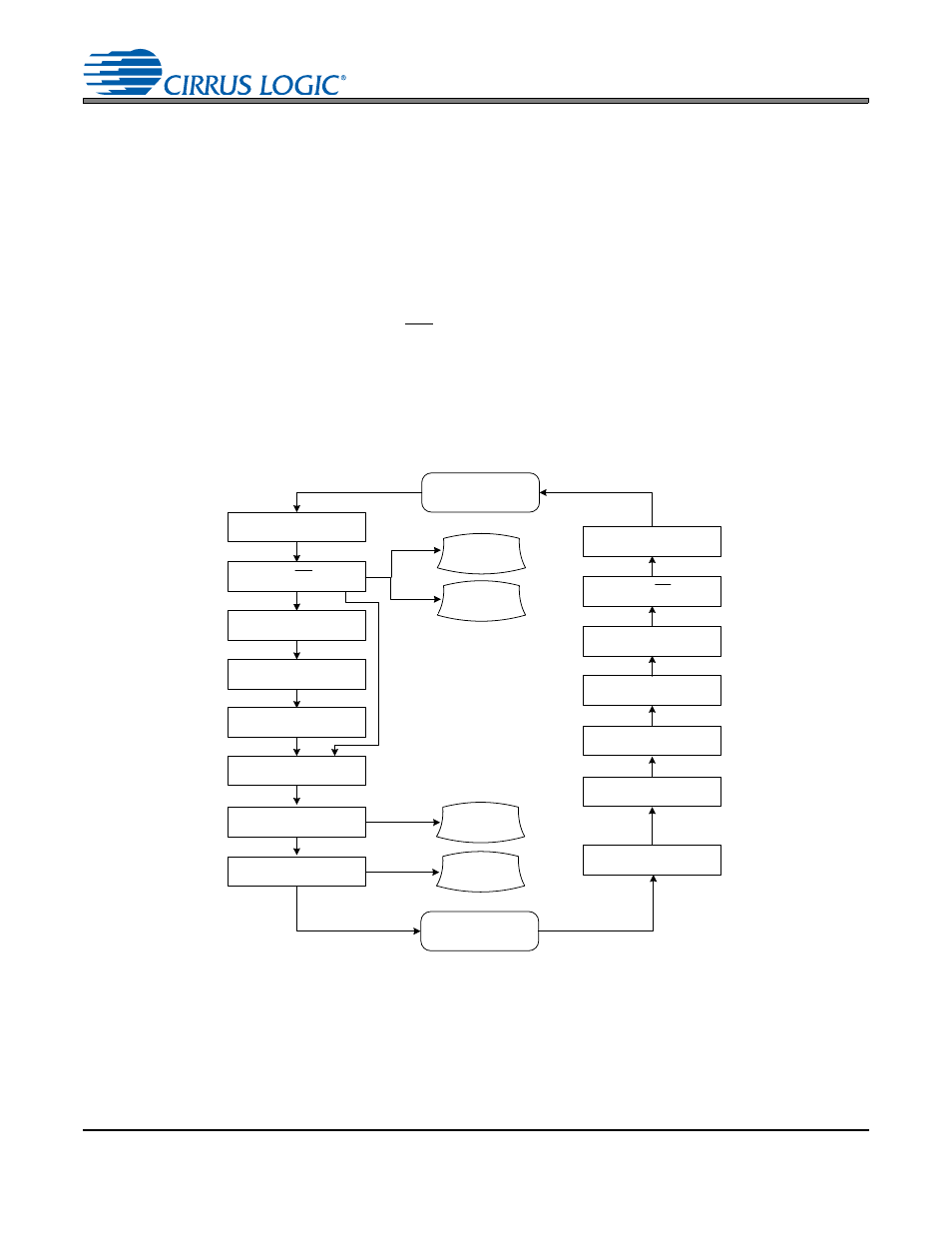
Figure 9. System Level Initialization and Power-Up/Down Sequence
4.2.3
DAC DC Loading
shows the analog output configuration during power-up, with the AOUTx± pins clamped to VQ
to prevent pops and clicks. Thus any DC loads (RL
x
) on the output pins will be in parallel when the switch-
es are closed. These DC loads will pull the VQ voltage down towards ground. If the parallel combination
of all DC loads exceeds the specification shown in the Analog Output Characteristics tables on pages
System
Operational
System
Unpowered
Set all PDN DAC & ADC bits
Stop SCLK, FS/LRCK, SDINx
Set VQ_RAMP bit
Remove VL, VA, and MCLK
Set Mute ADCx bits
Clear RST
DACx Fully
Operational
ADC Data
Available on
SDOUTx
2 ms + (3000/MCLK)
50 ms
Apply VL, VA, and MCLK
Clear PDN DACx & ADCx bits
Start SCLK, FS/LRCK, SDINx
Write all required configuration
settings to Control Port
Clear Mute DACx bits
Clear Mute ADCx bits
Set RST
VCM Ready
(>90% of Typical)
I
2
C Address
Captured & Control
Port Ready
250 ms
Write VA_SEL bit (in 0Fh)
appropriately for VA
delay dependent
on DAC mute /
unmute behavior
Set Mute DACx bits
delay dependent
on DAC mute /
unmute behavior
2 ms +
(3000 /MCLK)
250 ms