Cirrus Logic CS4244 User Manual
Cs4244, 4 in/4 out audio codec with pcm and tdm interfaces, Dac features
Copyright
Cirrus Logic, Inc. 2012
(All Rights Reserved)
4 In/4 Out Audio CODEC with PCM and TDM Interfaces
DAC Features
Advanced multibit delta-sigma modulator
24-bit resolution
Differential or single-ended outputs
Dynamic range (A-weighted)
–
-109 dB differential
–
-105 dB single-ended
THD+N
–
-90 dB differential
–
-88 dB single ended
2 Vrms full-scale output into 3-k
AC load
Rail-to-rail operation
ADC Features
Advanced multibit delta-sigma modulator
24-bit resolution
Differential inputs
-105 dB dynamic range (A-weighted)
-88 dB THD+N
2 Vrms full-scale input
System Features
TDM, left justified, and I²S serial inputs and outputs
I²C
TM
host control port
Supports logic levels between 5 and 1.8 V
Supports sample rates up to 96 kHz
Common Applications
Automotive audio systems
AV, Blu-Ray
®
, and DVD receivers
Audio interfaces, mixing consoles, and effects
processors
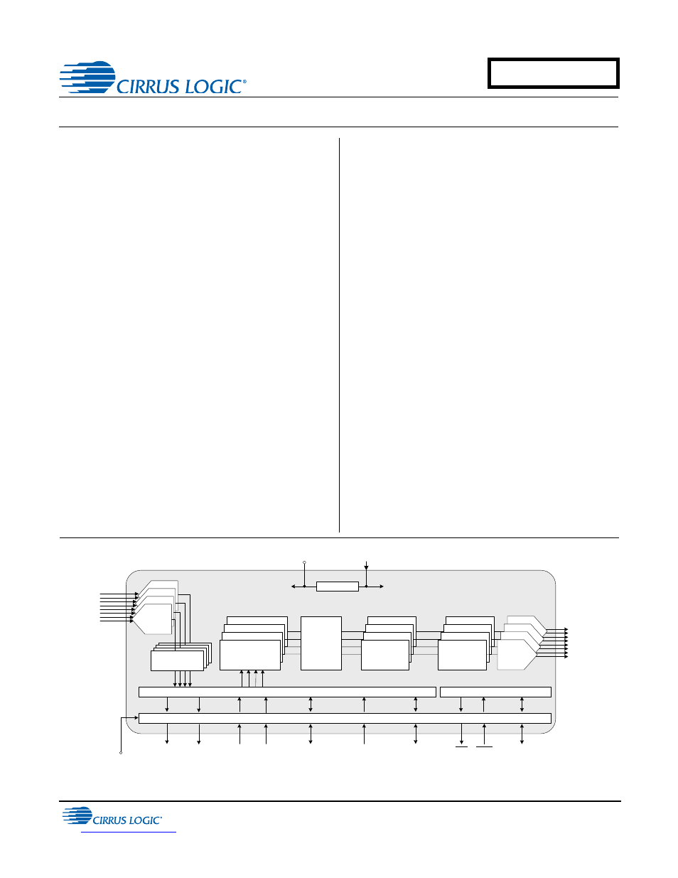
General Description
The CS4244 provides four multibit analog-to-digital and
four multi-bit digital-to-analog
- converters and is
compatible with differential inputs and either differential
or single-ended outputs. Digital volume control, noise
gating, and muting is provided for each DAC path. A se-
lectable high-pass filter is provided for the 4 ADC inputs.
The CS4244 supports master and slave modes and
TDM, left-justified, and I²S modes.
This product is available in a 40-pin QFN package in
Automotive (-40°C to +85°C) and Commercial (0°C to
+70°C) temperature grades. The CDB4244 Customer
Demonstration Board is also available for device evalu-
ation and implementation suggestions. See
for complete details.
AIN4 (±)
AIN3 (±)
AIN2 (±)
AIN1 (±)
I
2
C Control
Data
Control Port
Level Translator
VL
1.8 to 5.0 VDC
RST
INT
SDOUT1
LDO
Analog Supply
2.5 V
VA
5.0 VDC
VDREG
Serial Audio Interface
SDOUT2
AOUT1 (±)
AOUT2 (±)
AOUT3 (±)
AOUT4 (±)
Serial Clock
In/Out
Master Clock In
Frame Sync
Clock / LRCK
SDIN1
SDIN2
Digital Filters
Multi-bit
ADC
Interpolation
Filter
Multi-bit
Modulators
Channel Volume ,
Mute, Invert,
Noise Gate
DAC &
Analog
Filters
Master
Volume
Control
MAR ‘12
DS900F1
CS4244
Document Outline
- Table of Contents
- List of Figures
- List of Tables
- 1. Pin Descriptions
- 2. Typical Connection Diagram
- 3. Characteristics and Specifications
- Recommended Operating Conditions
- Absolute Maximum Ratings
- DC Electrical Characteristics
- Typical Current Consumption
- Analog Input Characteristics (Commercial Grade)
- Analog Input Characteristics (Automotive Grade)
- ADC Digital Filter Characteristics
- Analog Output Characteristics (Commercial Grade)
- Analog Output Characteristics (Automotive Grade)
- Combined DAC Interpolation & On-chip Analog Filter Response
- Digital I/O Characteristics
- Switching Characteristics - Serial Audio Interface
- Switching Specifications - Control Port
- 4. Applications
- 5. Register Quick Reference
- 6. Register Descriptions
- 6.1 Device I.D. A-F (Address 01h-03h) (Read Only)
- 6.2 Revision I.D. (Address 05h) (Read Only)
- 6.3 Clock & SP Select (Address 06h)
- 6.4 Sample Width Select (Address 07h)
- 6.5 Serial Port Control (Address 08h)
- 6.6 Serial Port Data Select (Address 09h)
- 6.7 ADC Control 1 (Address 0Fh)
- 6.8 ADC Control 2 (Address 10h)
- 6.9 DAC Control 1 (Address 12h)
- 6.10 DAC Control 2 (Address 13h)
- 6.11 DAC Control 3 (Address 14h)
- 6.12 DAC Control 4 (Address 15h)
- 6.13 Volume Mode (Address 16h)
- 6.14 Master and DAC1-4 Volume Control (Address 17h, 18h, 19h, 1Ah, & 1Bh)
- 6.15 Interrupt Control (Address 1Eh)
- 6.16 Interrupt Mask 1 (Address 1Fh)
- 6.17 Interrupt Mask 2 (Address 20h)
- 6.18 Interrupt Notification 1 (Address 21h) (Read Only)
- 6.19 Interrupt Notification 2 (Address 22h) (Read Only)
- 7. ADC Filter Plots
- 8. DAC Filter Plots
- 9. Package Dimensions
- 10. Ordering Information
- 11. Revision History