Figure 20, Cs4244, 2 dac1-4 signal routing – Cirrus Logic CS4244 User Manual
Page 32
DS900F1
32
CS4244
In Left Justified or I²S mode, the CS4244 transmits the AIN1 and AIN2 signals on the SDOUT1 pin and
the AIN3 and AIN4 signals on the SDOUT2 pin.
4.6.1.2
DAC1-4 Signal Routing
In TDM mode, the
“DAC1-4 SOURCE[2:0]” bits in the
advise the CS4244 where
data for the DAC1-4 path is located within the incoming TDM streams. Details for this register and the bit
settings can be found in
and
.
In Left Justified or I²S mode, the CS4244 routes the data on the SDIN1 pin to DAC1 and DAC2 and the
data on the SDIN2 pin to DAC3 and DAC4.
Device D
SDIN2
SDOUT1
SDIN1
x
x
Device A
SDIN2
SDOUT1
SDIN1
x
x
x
Device B
SDIN2
SDOUT1
SDIN1
x
x
x
Device C
SDIN2
SDOUT1
SDIN1
x
x
x
DSP
x
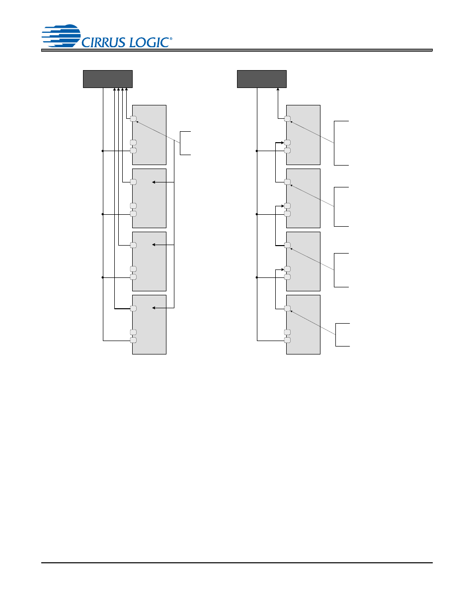
ADC data from Device A is loaded into the
first 4 slots of the 16 slot TDM Stream
going out of SDOUT1 pin of Device A. The
last 12 slots are all coded as “ 0's”.
The ADC data of Device B is coded into the
first four slots of the output TDM stream,
followed by the first 12 slots of the TDM
stream coming in on SDIN2, placing the
ADC data from Device A into slots 5-8 of the
outgoing TDM stream.
The ADC data of Device C is coded into the
first four slots of the output TDM stream,
followed by the first 12 slots of the TDM
stream coming in on SDIN2, placing the
ADC data from Device B into slots 5-8 and
the ADC data from Device A into slots 9-12
of the outgoing TDM stream.
The ADC data of Device D is coded into the
first four slots of the output TDM stream,
followed by the first 12 slots of the TDM
stream coming in on SDIN2, placing the
ADC data from Device C into slots 5-8, the
ADC data from Device B into slots 9-12, and
the ADC data from Device A into slots 13-16
of the outgoing TDM stream.
Device D
SDIN2
SDOUT1
SDIN1
x
x
Device A
SDIN2
SDOUT1
SDIN1
x
x
x
Device B
SDIN2
SDOUT1
SDIN1
x
x
x
Device C
SDIN2
SDOUT1
SDIN1
x
x
x
DSP
x
Each of the device’s ADC data
is reflected in the TDM stream
on SDOUT1 and then routed to
the system controller.
Note:
This diagram shows the configuration for 16 slot TDM streams. If 8 slot TDM streams are used, two separate serial data lines will need to be
connected from the DSP. One would carry the serial data for Devices C&D and the other would carry the serial data for Devices A&B
Figure 20. Conventional SDOUT (Left) vs. Sidechain SDOUT (Right) Configuration