WIKA HP-2 User Manual
Page 14
14
WIKA operating instructions pressure transmitter, model HP-2
11379180.03 09/2013 GB/D/F/E
GB
7. Adjustment of zero point and span
7. Adjustment of zero point and span
Only adjust the span-setting potentiometer if calibration equipment is avail-
able which has at least three times the accuracy of the pressure transmitter.
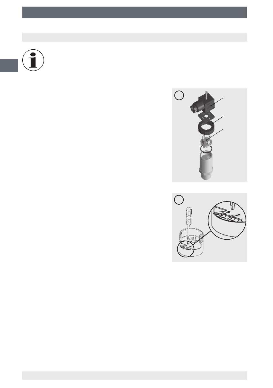
7.1 Preparation (figure A)
To gain access to the potentiometers, open the instru-
ment as follows:
■
Disconnect the electrical connection from the
instrument.
■
Remove the clamping nut .
■
Carefully pull the instrument connector from the
instrument.
■
Connect the instrument connector to the power
supply and a display unit (e.g. ammeter, voltmeter)
according to the connection diagram.
7.2 Adjustment of zero point (figure B)
■
Go to the start of the measuring range.
■
Using potentiometer “Z”, adjust the minimum output
signal (e.g. 4 mA).
7.3 Setting the span (figure B)
■
Go to the end of the measuring range.
■
Using potentiometer “S”, adjust the maximum output
signal (e.g. 20 mA).
■
Check the zero point and if there is any deviation,
re-adjust it.
■
Repeat the procedure until the zero point and the
span are set correctly.
7.4 Finish the adjustment (figure A)
■
Disconnect the instrument connector from the power supply and the display unit.
■
Carefully push the instrument connector onto the instrument, without damaging the
wires or the seals. The seals must be clean and undamaged in order to guarantee the
given ingress protection.
■
Tighten the clamping nut .
After the adjustment, check that the system is functioning correctly.
Recommended recalibration cycle: Half-yearly
A
B