Gb 6. commissioning, operation – WIKA HP-2 User Manual
Page 13
13
WIKA operating instructions pressure transmitter, model HP-2
11379180.03 09/2013 GB/D/F/E
GB
6. Commissioning, operation
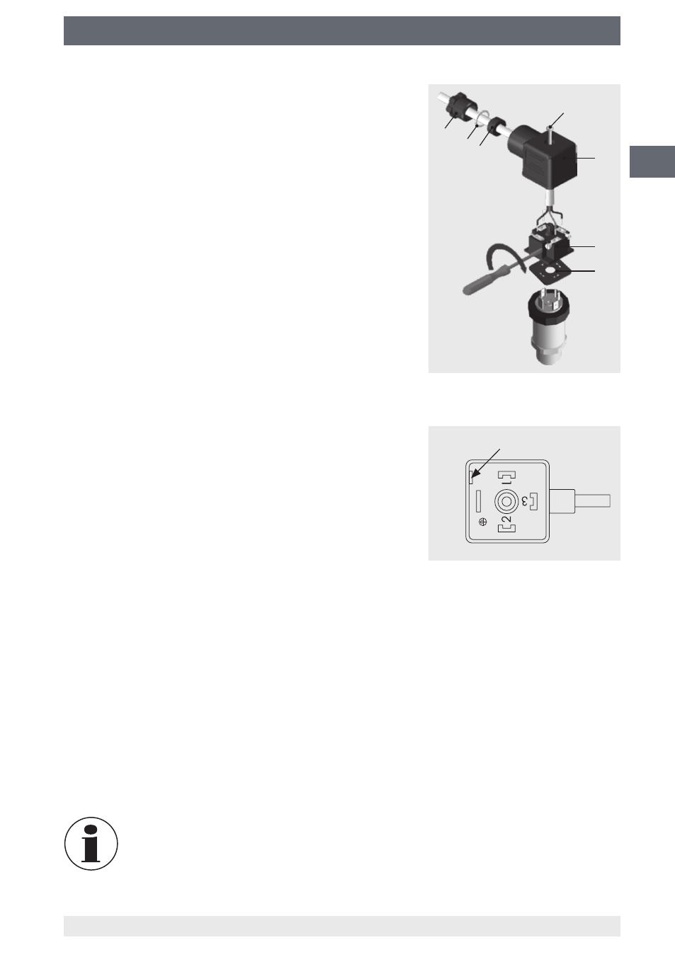
Fitting the DIN 175301-803 angular connector
1. Loosen the screw .
2. Loosen the cable gland .
3. Pull the angled socket + from the instrument.
4. Via the mounting hole , lever the terminal block
out of the case .
5. Pass the cable with the appropriate cable outer
diameter through the cable gland , ring ,
sealing and the case .
6. Connect the cable ends to the connection termi-
nals on the terminal block in accordance with the
pin assignment (see “Connection diagrams” for the
pin assignment).
7. Press the terminal block into the case .
8. Tighten the cable gland around the cable.
Make sure that the cable gland and seal are not
damaged and that they are assembled correctly in
order to ensure ingress protection.
9. Place the flat, square gasket over the pressure
transmitter's connection pins.
10. Slide the assembled angled socket + onto
the pressure transmitter's connection pins.
11. Using the screw , screw the angled socket to the
pressure transmitter, hand-tight.
6.3 Commissioning of USB instruments
■
For installing the driver, administrator rights are required.
■
Connect the USB connector to a USB 2.0 port at your computer.
■
Install the driver via the InstallWizard of the product software.
■
For further operation the P-3x data logger software is available (for details see
instruction manual P-3x data logger).
■
Details on the interface protocol or the DLL (Dynamic Link Library) are available on
the software CD and in the download section at www.wika.com.
For the model HP-2, model P-30 software must be used. All files and
documents are available for download at www.wika.com.
Mounting hole