Figure 15: operating a set of three switchers – Kramer Electronics VS-812 User Manual
Page 21
KRAMER: SIMPLE CREATIVE TECHNOLOGY
Operating Your Composite / s-Video / Audio Switcher
18
7.1.3
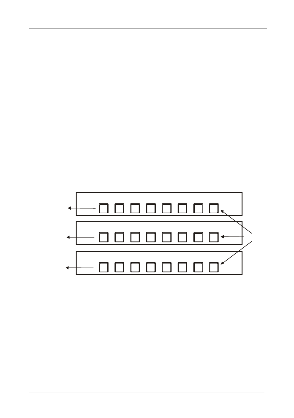
Selecting a CV or a Y/C Source on a Set of three VS-812 Units
When operating, for example, a set of three looped VS-812 units, not all the
INPUT SELECTOR buttons on the front panels of the combined VS-812
units are active. For example, as
illustrates, with a combination of
three switchers, you cannot use all the eight INPUT SELECTOR buttons on
each looped VS-812 unit. INPUT SELECTOR button 8 on the first, second
and third units are inactive. You cannot connect CV IN 8 on the first and
second units to an independent source because CV IN 8 on the first unit is
connected to OUT 1 on the second unit and CV IN 8 on the second unit is
connected to OUT 1 on the third unit. Similarly, you cannot connect Y/C IN 8
on the first and second units to an independent source because Y/C IN 8 on
the first unit is connected to OUT 1 on the second unit and Y/C IN 8 on the
second unit is connected to OUT 1 on the third unit.
INPUT SELECTOR buttons marked 1 to 7 on the first looped VS-812 unit
operate CV / Y/C inputs 1 to 7, respectively. INPUT SELECTOR buttons
marked 1 to 7 on the second looped VS-812 unit operate CV / Y/C inputs 8 to
14, respectively. INPUT SELECTOR buttons marked 1 to 7 on the third
looped VS-812 unit operate CV / Y/C inputs 15 to 21, respectively.
1
2
3
4
5
6
7
8
INPUT SELECTOR
1
2
3
4
5
6
7
8
INPUT SELECTOR
1
2
3
4
5
6
7
8
INPUT SELECTOR
Inactive
INPUTS 1 to 7
INPUTS 8 to 14
INPUTS 15 to 21
X
X
X
Figure 15: Operating a Set of three Switchers
To operate the INPUT SELECTOR buttons on a combination of three
VS-812 units:
• Press an active INPUT SELECTOR button on the front panel of one of
the looped VS-812 units
The active INPUT SELECTOR button illuminates and switches that input
to the output