Table 3 – Kramer Electronics VS-812 User Manual
Page 17
KRAMER: SIMPLE CREATIVE TECHNOLOGY
Connecting the VS-812 8x1 Composite / s-Video / Audio Switcher
14
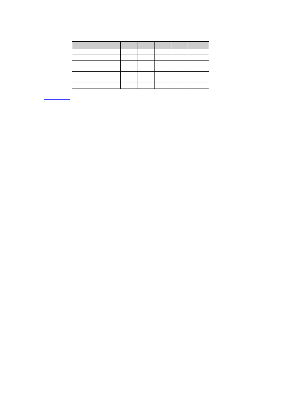
Table 3: MACHINE ADDRESS # DIP-switch Settings for a Set of VS-812 Units
MACHINE ADDRESS #
DIP 1
DIP 2
DIP 3
DIP 4
INPUT #
1
ON
OFF
OFF
ON
1-7
2
OFF
ON
OFF
ON
8-14
3
ON
ON
OFF
ON
15-21
4
OFF
OFF
ON
ON
22-28
5
ON
OFF
ON
ON
29-35
6
OFF
ON
ON
ON
36-42
7
ON
ON
ON
ON
43-49
illustrates how to connect and how to set the DIP-switches on a set
of three looped VS-812 units (with DIP 4 ON) and on an independent VS-812
unit (with DIP 4 OFF), which are controlled by one RS-232 port.
To connect the set of three looped VS-812 units:
1. Connect the CV OUT 1 connector and the OUT 1 Audio (CV) connector on
the first VS-812 unit to the CV video acceptor.
2. Connect the Y/C OUT 1 connector and the OUT 2 Audio (Y/C) connector on
the first VS-812 unit to the Y/C video acceptor.
3. Connect the CV OUT 1 connector on the second VS-812 unit to the CV IN 8
connector on the first VS-812 unit and connect the OUT 1 Audio (CV)
connector on the second VS-812 unit to the IN 8 Audio (CV) connector on the
first VS-812 unit.
4. Connect the Y/C OUT 1 connector on the second VS-812 unit to the Y/C IN 8
connector on the first VS-812 unit and connect the OUT 2 Audio (Y/C)
connector on the second VS-812 unit to the IN 8 Audio (Y/C) connector on the
first VS-812 unit.
5. Connect the CV OUT 1 connector on the third VS-812 unit to the CV IN 8
connector on the second VS-812 unit and connect the OUT 1 Audio (CV)
connector on the third VS-812 unit to the IN 8 Audio (CV) connector on the
second VS-812 unit.
6. Connect the Y/C OUT 1 connector on the third VS-812 unit to the Y/C IN 8
connector on the second VS-812 unit and connect the OUT 2 Audio (Y/C)
connector on the third VS-812 unit to the IN 8 Audio (Y/C) connector on the
second VS-812 unit.
You can switch any one of the 21 CV inputs to the CV video acceptor and any
one of the 21 Y/C inputs to the CV video acceptor.