2 shorting jumpers jmp4 and jmp5, Shorting jumpers jmp4 and jmp5, Setting the dip-switches on a set of vs-812 units – Kramer Electronics VS-812 User Manual
Page 16: Figure 11: location of jumpers jmp4 and jmp5, Ustrated in, Figure 11, Refer to section
Connecting the VS-812 8x1 Composite / s-Video / Audio Switcher
13
13
6.3.2
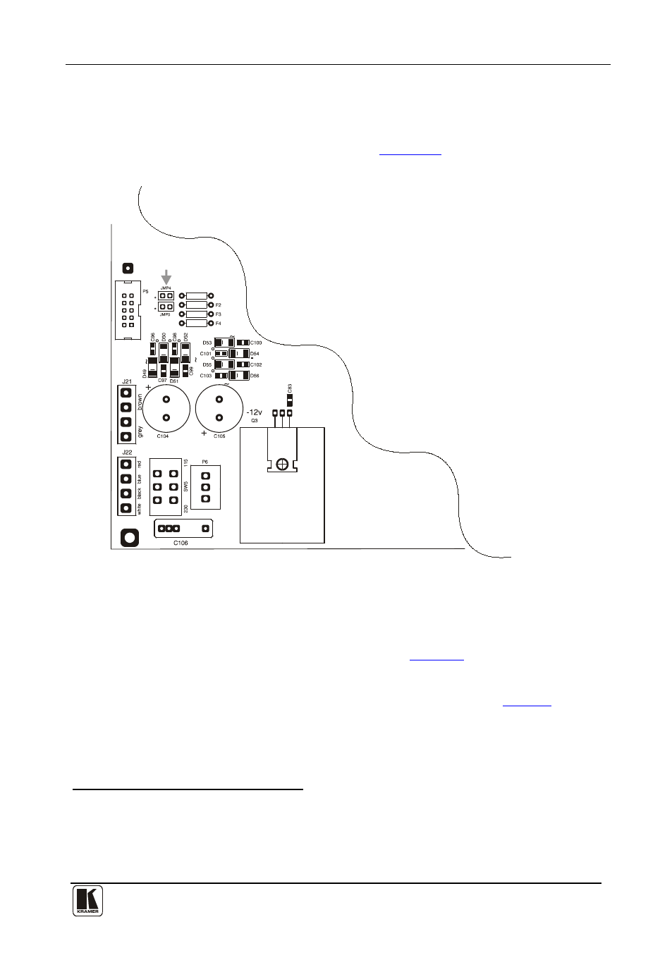
Shorting Jumpers JMP4 and JMP5
When connecting a PC to a set of VS-812 units you need to adjust the factory
default by opening each VS-812 unit, shorting (closing) Jumpers JMP4 and
JMP5, and then closing each VS-812 unit.
Jumpers JMP4 and JMP5:
Jumpers,
JMP 4/5
Figure 11: Location of Jumpers JMP4 and JMP5
6.3.3
Setting the DIP-switches on a Set of VS-812 Units
Cascading up to seven VS-812 units
requires using all 4 DIP-switches
,
located on the underside of the VS-812 unit, as
• Every VS-812 unit that forms part of the set, as MACHINE # 8
• The MACHINE ADDRESS #
using DIPS 1, 2, and 3, as
1 To form a set of VS-812 units with seven inputs on each of the VS-812 units
2 Setting DIP 4 ON to notify the VS-812 unit that it forms part of a set of VS-812 units
3 Set the MACHINE ADDRESS # on each VS-812 unit that is included in a set, to define its position in the extended
switcher system, specifying which VS-812 unit within the set is being controlled