1 preparing the rs-232 connectors, Preparing the rs-232 connectors, Figure 10: preparing the rs-232 connectors – Kramer Electronics VS-812 User Manual
Page 15
KRAMER: SIMPLE CREATIVE TECHNOLOGY
Connecting the VS-812 8x1 Composite / s-Video / Audio Switcher
12
6.3.1
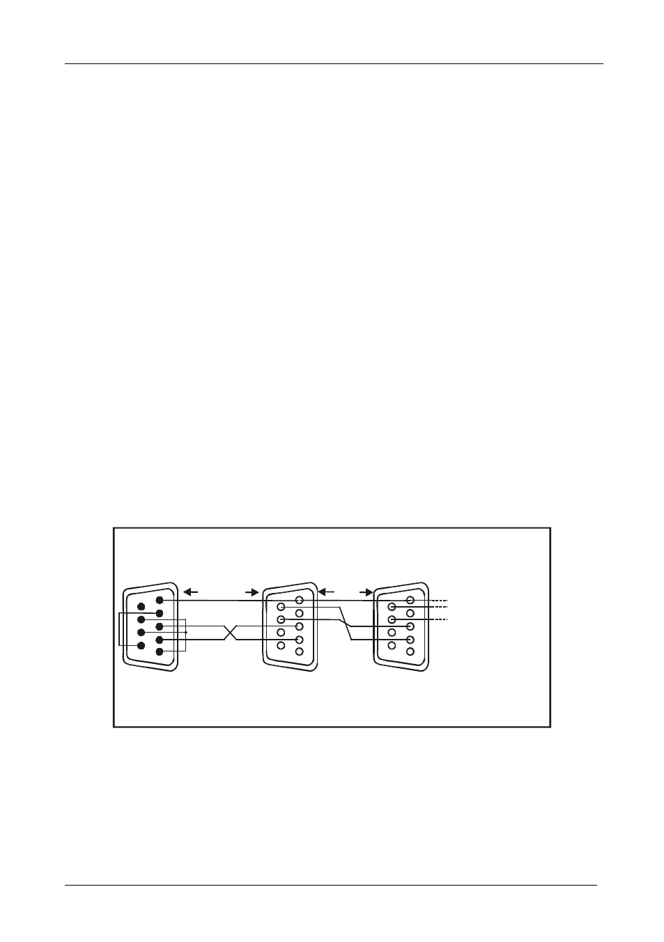
Preparing the RS-232 Connectors
To connect a PC to a set of VS-812 units, do not use a Null-modem adapter.
Do the following:
1. Prepare the RS-232 9-pin D-sub connector (A), by connecting PIN 4 to
PIN 6 and connecting PINS 8, 7, and 1 together.
2. Attach the RS-232 9-pin D-sub connector (A) to another RS-232 9-pin
D-sub M connector (B) by connecting PIN 5 to PIN 5, PIN 3 to PIN 2,
and PIN 2 to PIN 3.
3. Connect the RS-232 9-pin D-sub connector (A) to your PC’s RS-232
9-pin D-sub M port.
4. Attach the RS-232 9-pin D-sub M connector (B) to another RS-232 9-pin
D-sub M connector (C), by connecting PIN 5 to PIN 5, PIN 8 to PIN 3,
PIN 9 to PIN 2.
5. Connect the RS-232 9-pin D-sub M connector (B) to the RS-232 9-pin
D-sub port on the first VS-812 unit.
6. Attach the RS-232 9-pin D-sub M connector (C) to another RS-232 9-pin
D-sub M connector, if required, by connecting PIN 5 to PIN 5, PIN 8 to
PIN 3, PIN 9 to PIN 2.
7. Connect the RS-232 9-pin D-sub M connector (C) to the RS-232 9-pin
D-sub port on the next VS-812 unit.
To First VS-812
Unit (
M)
9-pin D-sub
1
2
3
4
5
6
7
8
9
To the Next VS-812
Unit (
M)
9-pin D-sub
1
2
3
4
5
To PIN 2
To PIN 5
PIN 5 Connected to PIN 5 (Ground)
PIN 3 Connected to PIN 2
PIN 2 Connected to PIN 3
PIN 5 Connected to PIN 5 (Ground)
PIN 8 Connected to PIN 3
PIN 9 Connected to PIN 2
To PIN 3
6
7
8
9
1
2
3
4
5
6
7
8
9
A
B
Up to 15 Meters
Up to
15 Meters
To PC (9-pin D-sub F)
PIN 4 Connected to PIN 6
PINS 8, 7, 1 Connected together
To Next VS-812
Unit (
M)
9-pin D-sub
…
C
Figure 10: Preparing the RS-232 Connectors