3 connecting a set of vs-812 units to a pc, Connecting a set of vs-812 units to a pc, Figure 9 – Kramer Electronics VS-812 User Manual
Page 14: Figure 9 illustrates how to set the dip-switches
Connecting the VS-812 8x1 Composite / s-Video / Audio Switcher
11
11
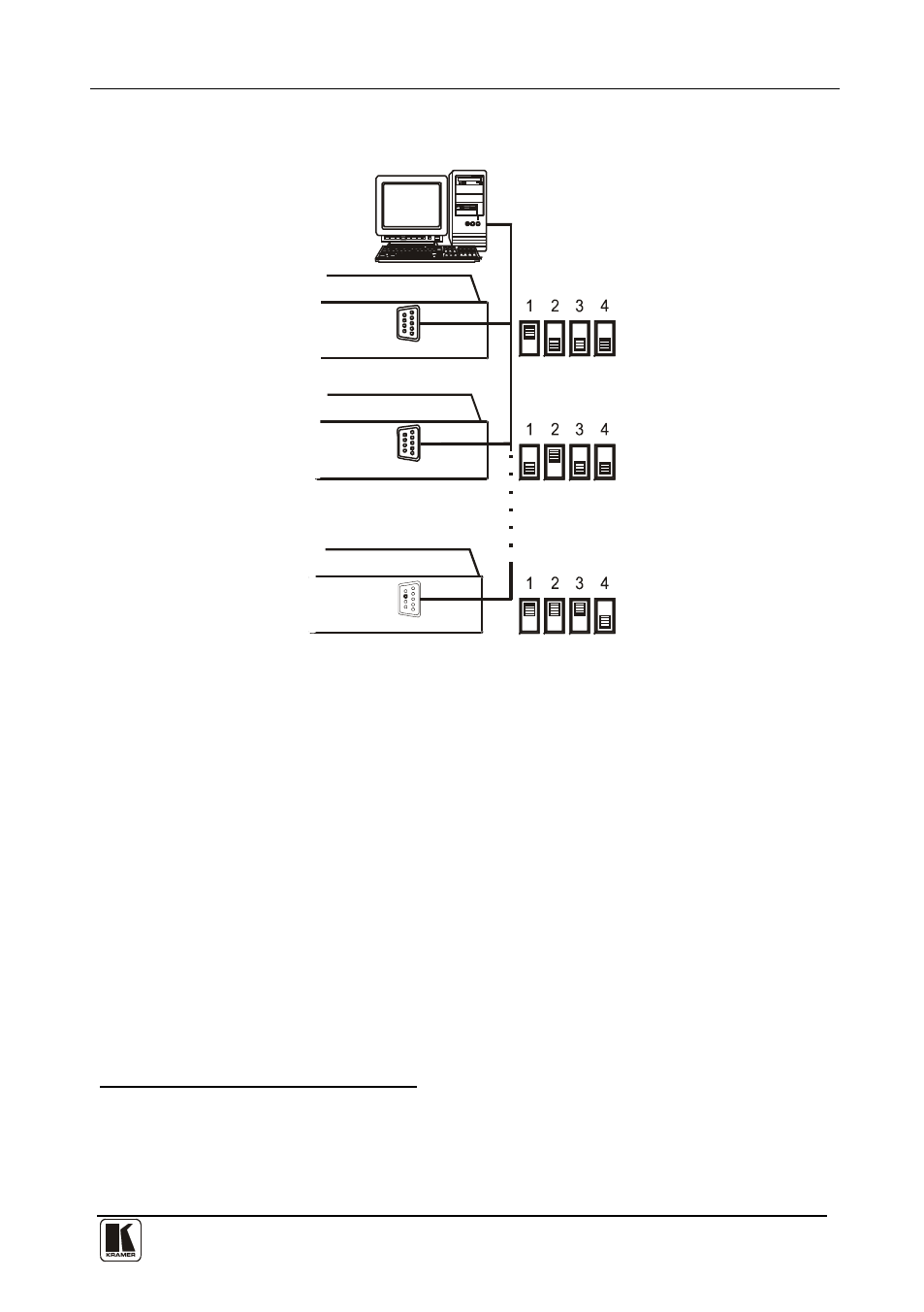
Figure 9 illustrates how to set the DIP-switches
DIP-switches
MACHINE # 1
MACHINE # 2
MACHINE # 7
RS-232
Up to 7 Units
RS-232
VS-812
RS-232
VS-812
VS-812
on up to seven independent
VS-812 units, which are controlled by one RS-232 port:
Figure 9: DIP-switch Settings on 7 Independent VS-812 Units
6.3 Connecting a Set of VS-812 Units to a PC
Connecting a set
of VS-812 units enables you to connect several VS-812
units to form a combined VS-812 unit with expanded inputs
This section describes preparing the RS-232 connectors, shorting Jumpers
JMP4 and JMP5, and setting the DIP-switches on a set of VS-812 units.
and/or connect
several individual VS-812 (or other Kramer) units to the same RS-232 line.
1 Set DIP-switch 4 OFF and set the MACHINE # according to each VS-812 unit’s position in the sequence
2 You can only connect one set of VS-812 units to the same RS-232 line
3 By looping 7 VS-812 units you provide up to 49 CV inputs and up to 49 Y/C inputs. You can also connect up to seven
standalone VS-812 units together with these seven looped VS-812 units, to the same RS-232 line