2 adjusting jumpers jmp4 and jmp5, Adjusting jumpers jmp4 and jmp5, Figure 7 – Kramer Electronics VS-812 User Manual
Page 12: Define, Figure 6, Jumpers jmp4 and jmp5
Connecting the VS-812 8x1 Composite / s-Video / Audio Switcher
9
9
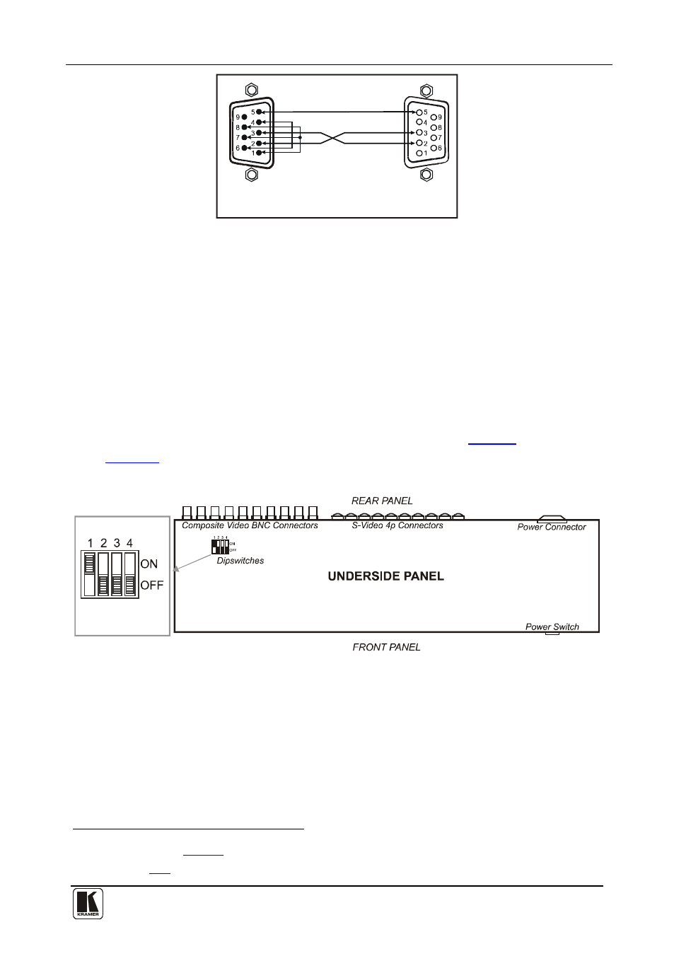
9-pin D-sub
(From PC)
9-pin D-sub
(Male)
If a shielded cable is used, connect the shield to PIN 5
PIN 4 is connected to PIN 6
PINs 8, 7, 1 are connected together
PIN 5 Connected to PIN 5 (Ground)
PIN 3 Connected to PIN 2
PIN 2 Connected to PIN 3
Figure 6: Connecting to a PC without using a Null-modem Adapter
6.2.2
Adjusting Jumpers JMP4 and JMP5
Jumpers JMP4 and JMP5
• Open (the factory default) - when using that VS-812 unit as an
independent VS-812 unit
on the board inside a VS-812 unit, should be:
• Closed - when using that VS-812 unit as a VS-812 unit that forms part of
a set of VS-812 units
6.2.3
Setting the DIP-switches on an Independent VS-812 Unit
The VS-812 unit includes a set of four DIP-switches, as
illustrates the location of the DIP-switches on the underside of the
VS-812 unit:
Enlarged View
For MACHINE # 1, set
DIPS
2, 3, and 4 OFF
DIP 2 ON and
Figure 7: Location of the DIP-switches on a VS-812 Unit
1 Located as illustrated in