3 ethernet port configuration and control – Kramer Electronics VP-771 User Manual
Page 59
54
VP-771 - Controlling the VP-771
8.3.3.3 Ethernet Port Configuration and Control
Use the Kramer K-UPLOAD software to configure and control the VP-771 via the
Ethernet.
The latest version of K-UPLOAD and installation instructions can be
downloaded from the Kramer Web site at
8.4
Controlling the VP-771 via the REMOTE Terminal Block
Connector
The REMOTE terminal block connectors include:
A PIP pin and a G pin which are used for toggling between the Single and
Dual window modes, and for selecting a PiP input
Nine input pins (defined in the table below) and a G pin for selecting an input
PIN#
Input Source
PIN#
Input Source
PIN#
Input Source
1
HDMI 1
4
PC 2
7
CV 2
2
HDMI 2
5
COMP.
8
DP
3
PC 1
6
CV 1
9
SDI
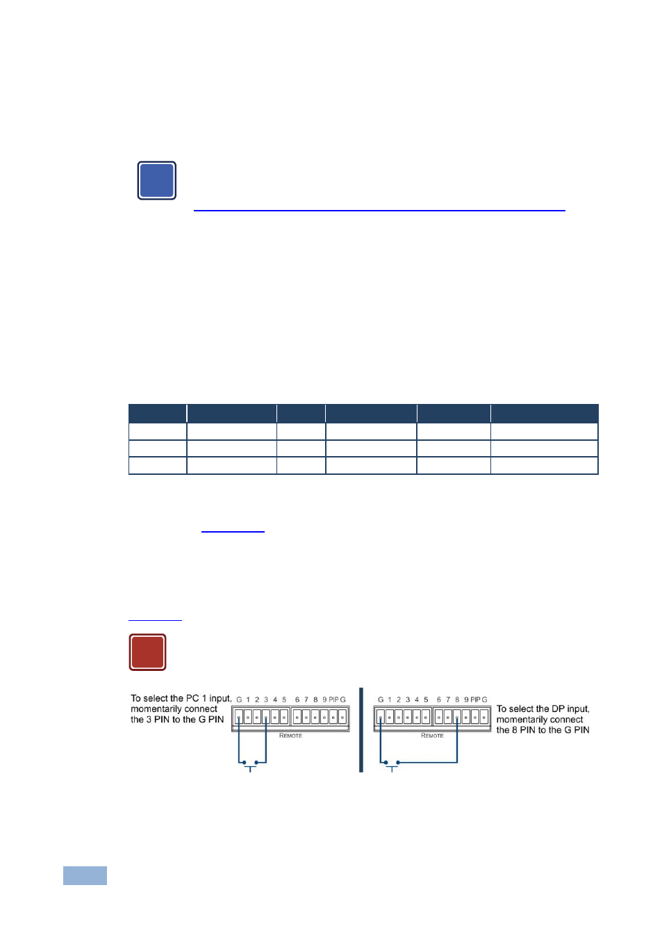
The contact closure remote control pins operate in a similar way to the INPUT
buttons (see
Section
). Using the contact closure remote control (also known as
push-to-make momentary contact) you can select any of the inputs. To do so,
momentarily connect the required input pin (1 to 9) on the REMOTE terminal block
connector to the G (Ground) pin of the REMOTE terminal block connector, as
illustrates.
Do not connect more than one input PIN to the GND PIN at the same
time.
Figure 34: Connecting the Contact Closure Remote Control PINs
i
!