5 connecting the vp-771, Connecting the vp-771, Figure 3: 15-pin hd connector pinout – Kramer Electronics VP-771 User Manual
Page 17: 5connecting the vp-771
12
VP-771 - Connecting the VP-771
5
Connecting the VP-771
Always switch off the power to each device before connecting it to
your VP-771. After connecting your VP-771, connect its power and
then switch on the power to each device.
You do not have to connect all the inputs and outputs, connect only
those that are required.
To connect the VP-771, as illustrated in the example in
, do the following:
1. Connect an HDMI source (for example, a DVD player) to the HDMI 1 IN
VIDEO INPUT connector.
Alternatively, you can connect the DVI connector on the DVD player to the HDMI
connector on the VP-771 via a DVI-HDMI adapter. You can connect the audio signal via
the AUDIO IN HDMI 3.5mm mini jack, or use the embedded audio
2. Connect a computer graphics source to the PC 1 IN VIDEO INPUT 15-pin
HD connector.
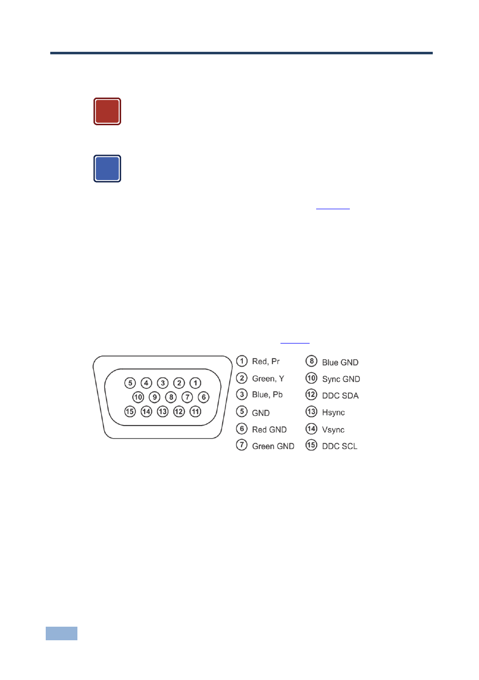
Alternatively, you can connect a component (YPbPr) or RGBHV source via the 15-pin
HD connector (available for PC1 IN only), see
Figure 3: 15-pin HD Connector Pinout
3. Connect a component video source (for example, a component DVD player)
to the COMP P
R
, P
B
and Y, VIDEO INPUT RCA connectors.
4. Connect a composite video source (for example, a composite video player)
to the CV VIDEO INPUT RCA connector.
5. Connect a DisplayPort video source (for example, a computer graphics
source) to the DISPLAYPORT connector.
!
i