Wiring the tp line in / line out rj-45 connectors, Figure 5: tp pinout – Kramer Electronics VP-771 User Manual
Page 20
VP-771 - Connecting the VP-771
15
15
5.1
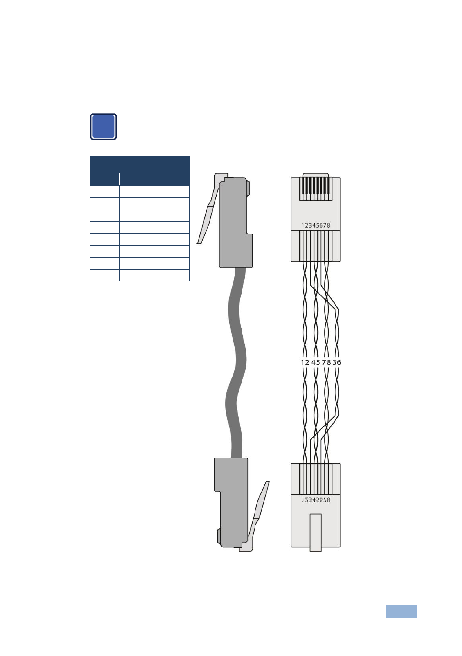
Wiring the TP LINE IN / LINE OUT RJ-45 Connectors
This section defines the TP pinout, using a straight pin-to-pin cable with RJ-45
connectors.
Note, that the cable Ground shielding must be connected / soldered to
the connector shield.
EIA /TIA 568B
Figure 5: TP PINOUT
PIN
Wire Color
1
Orange / White
2
Orange
3
Green / White
4
Blue
5
Blue / White
6
Green
7
Brown / White
8
Brown
i