Myron L 729II User Manual
Page 54
50
figure V.A.1 for location of items described below. A DVM set to
DC Volts is required.
Note: For digital panel display perform step 8.
For analog meter display adjust DISplay calibration
control pot instead and DO NOT perform step 13
1. Ensure power is OFF.
2. Attach DVM to RECORDER output connection.
3. Turn power ON.
4. Press and hold the ZERO test switch.
5. The DVM should indicate 5.00VDC.
6. If not, adjust ZERO calibration control until DVM
indicates 5.00VDC.
7. Verify the panel meter/display, should indicate 0mV.
8. If not, adjust ORP ZERO control until display indicates
0mV.
9. Press and hold SPAN test switch.
10. The DVM should indicate 0VDC.
11. If not, adjust SPAN calibration control until DVM
indicates 0VDC.
12. Verify the panel meter/display, it should indicate
-1999mV.
13. If not, adjust DISplay control until display indicates
-1999mV.
14. Turn power OFF.
15. Re-install front panel as described in
“REASSEMBLY”, page 54.
3. CALIBRATION USING BUFFER SOLUTIONS
The BEST method of calibrating your pH or ORP Monitor/controller
is with NIST traceable Buffer Solutions (available from the Myron
L Company). Because it includes the sensor, the entire system is
calibrated.
For ORP, use 7pH buffer solution to set 0mV. Where 4 or 10 buffer
is referenced substitute ORP solution, or use the internal
-1999mV calibration.
1. Rinse a clean glass beaker thoroughly with 7pH buffer
solution.
2. Fill beaker with 7pH buffer solution.
3. Place sensor in the beaker of buffer solution. Level of
buffer solution must be at least 1” above the sensor tip.
4. Carefully shake the sensor to remove air bubbles from
around the sensor tip area.
5. Allow 5-10 minutes for temperature to equilibrate. For the
quickest and the best results, both the sensor and
solution should be at the same temperature.
6. Read the panel meter/display. The display should match
the value and units of measure shown on the bottle of
buffer solution. If the reading is different, adjust ZERO
calibration control on the main control circuit board
until reading is 7pH or 0mV.
7. Repeat steps 2 - 5. using either 4 or 10 pH buffer
solution. If reading is incorrect, adjust SPAN
calibration control on the main control circuit board
until reading matches buffer solution.
8. Turn OFF power.
9. Re-install front panel as described in
“REASSEMBLY”, page 54.
4. SENSOR SUBSTITUTE CALIBRATION
A compatible NIST traceable sensor substitute or adapter is
available from the Myron L Company. This is normally not
necessary due the “internal” electronic calibration. However, your
requirements may be such that a crosscheck or verification is
essential. The following will step you through the procedure.
NOTE: if you have previously performed a calibration with a
buffer solution this procedure will make that calibration invalid.
You must decide which is more important, a true calibration with
a buffer solution, or an electronic calibration.
1. Ensure power OFF.
2. Using a standard slot screwdriver remove the
screws on the front panel.
3. Carefully wiggle the front panel to loosen the gasket and
pull gently toward you. Do not pull more than about 8
inches/20cm or you could damage the wiring harness.
4. Turn the front panel around so that the back side is
facing you and set aside.
5. Locate and remove the sensor leads from the sensor
connector as shown in figure V.A.1.
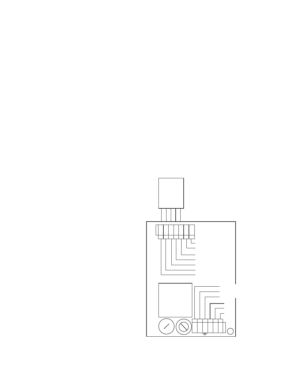
6. Install sensor substitute as shown in figure V.C.1. with
sensor substitute label toward the transformer.
7. Turn power ON.
8. Set substitute to 7pH or 0mV.
9. If necessary, adjust ZERO calibration control until
reading is 7pH or 0mV.
10. Reset substitute to either 4pH or 10pH (-177 or +177mV).
11. If necessary, adjust SPAN calibration control until
reading is 7pH or 10pH (-177 or +177mV).
12. After adjustment, turn power OFF.
13. Re-install front panel as described in
“REASSEMBLY”, page 54.
ALARM
CONTROL
RELAY
MAIN
INPUT
POWER
HOT-BLK/+DC
NEU-WHT/-DC
GND-GRN
}
}
Figure V.C.1.
ELECTRICAL CONNECT DIAGRAM
CHASSIS GROUND for
OEM INSTALLATIONS ONLY
FUSE
115/230
SWITCH
L N
NC
NO
COM
0-10VDC
OUTPUT
NEU
GRN
RED
WHT
BLK
(+)
(-)
}
}
SENSOR SUBSTITUTE
LABEL TOWARD
TRANSFORMER
TRANSFORMER
SENSOR
SE
NS
O
R
SU
BS
TI
TU
TE
LA
BE
L