Myron L 729II User Manual
Page 16
E.
ELECTRICAL INSTALLATION
The electrical installation procedures provided in this manual are
common to all pH & ORP Monitor/controllers. See figure II.B.1 for
the hole dimensions of the enclosure’s cable access holes.
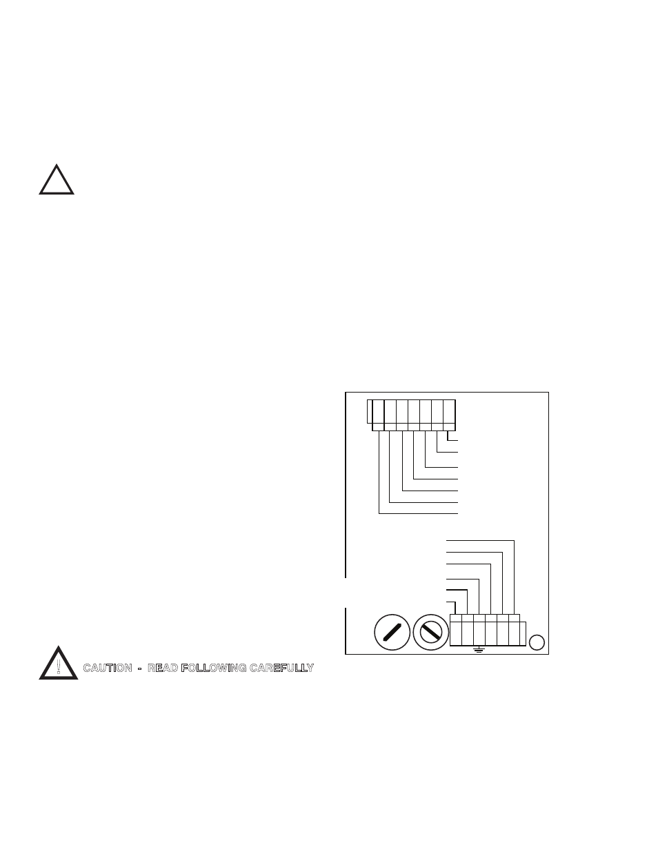
Unless otherwise instructed, refer to figure II.E.1. for the 720
Series II Monitor’s terminal block connector wiring designations.
NOTE: After removing an enclosure’s access hole plug, it is
suggested that the user mount a watertight restraint fixture prior
to installing a cable.
A device to disconnect the Model 720II from the
power supply is required. It is recommended that
this switch or circuit breaker be labeled as the
disconnection device for the Model 720II.
1. MAIN INPUT POWER INSTALLATION
WARNING: All Monitor/controllers are factory set for
115 VAC. Before starting, ensure the input power
“115/230” selection is correct for your requirements.
Failure to do so is beyond the responsibility of the
Myron L Company. See section II.E.2 below and
figure II.E.1.
NOTE: Some models may have either a 24 VAC or a
24 VDC input power requirement - check labels
carefully.
1. Verify that the main power source is turned “OFF” or
disconnected.
2. Using a standard slot screwdriver remove the
screws on the front panel.
3. Carefully wiggle the front panel to loosen the gasket and
pull gently toward you. Do not pull more than about 8
inches/20CM or you could damage the wiring harness.
4. Turn the front panel around so that the back side is
facing you and set aside for now.
5. Carefully remove front panel, leaving the harness
connected. For OEM models skip to step #4.
6. Using the enclosure cutouts, install the proper wire and
watertight cable restraint (not provided) to comply with
local electrical codes. Skip for OEM.
7. Neatly connect wires to the Monitor/controller’s
connectors, as shown in figure II.E.1.
*CAUTION: The input power connectors require only a small
screwdriver or a pen to push on the release levers. The release
levers may be broken or damaged if not pushed straight toward
the circuit board. DO NOT push the release levers sideways.
2. 115/230 VAC CONVERSION
1. Before turning power on to the Monitor/controller ensure
the proper input voltage has been selected. Failure to do
so will blow the fuse. It could, under some conditions,
cause injury and damage the instrument voiding the
warranty.
2. Locate switch located next to the fuse holder.
3. Using a screwdriver, turn switch to required voltage.
3. CONNECTING THE SENSOR CABLE
For OEM models skip #1.
A 10 ft/3 meter sensor cable length is standard. 25 ft/7.5 meter and
100 ft/30 meter cable lengths are available as options. The sensor
cable may be extended up to 1000 feet/300 meters by ordering
cable only. It is recommended proper water tight and shielding
methods (i.e. junction box) be used when extending the cable.
Cable only: Part Number pHCRD-(length)
Example: pHCRD-300 (90m)
NOTE: 1000 ft/300 meter cable lengths have been tested with
no adverse affects on the readings. However, unusual conditions
may be experienced when extended long distances, i.e. power or
ground reversal. These conditions are beyond the control and
responsibility of the Myron L Company. A clean installation is
required. If you are experiencing errors, check the
Monitor/controller with a 10 ft/3 meter cable before contacting your
distributor or the Myron L Company.
1. Place the sensor cable and user supplied watertight
cable restraint into the enclosure’s appropriate access
hole.
2. Install the sensor cable wire to comply with local
electrical codes. Follow the color code as marked. See
figure II.E.1.
CAUTION: The circuit board connectors require only a small
screwdriver or a pen to push on the release levers. The release
levers may be broken or damaged if not pushed straight toward
the circuit board. DO NOT push the release levers sideways.
a. MODIFICATION FOR US PHARMACEUTICAL
25 (No Temperature Compensation)
This simple modification will allow your Monitor/controller to meet
the USP 25 requirements by disabling the normal temperature
compensation circuit thus giving “uncompensated” readings as
required.
12
!
WARNING !
!
CAUTION - READ FOLLOWING CAREFULLY
ELECTRICAL CONNECT DIAGRAM
CHASSIS GROUND for
OEM INSTALLATIONS ONLY
SENSOR
L N
0-10VDC
OUTPUT
NEU
GRN
RED
WHT
BLK
(+)
(-)
ALARM
CONTROL
RELAY
COM
NO
NC
MAIN
INPUT
POWER
GND-GRN
NEU-WHT / -DC
LINE-BLK/ +DC
{
}
{
}
FUSE
115/ 230
SWITCH
Figure II.E.1