Myron L 729II User Manual
Page 17
Specifications:
As required to meet USP 25.
Installation
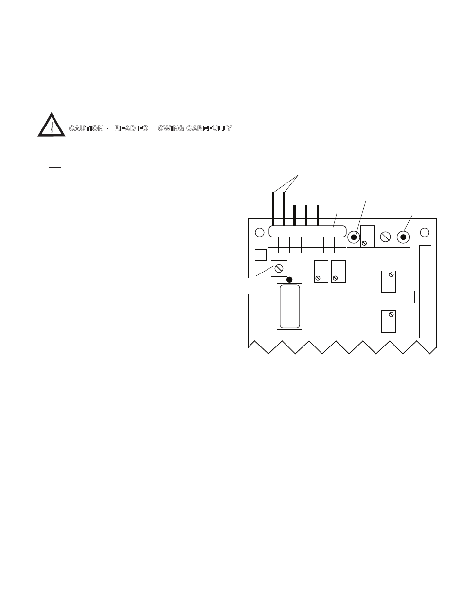
Briefly -
The BLACK and WHITE sensor leads are REVERSED in the
sensor connector.
Requirements:
None
WARNING: BEFORE STARTING, IF MONITOR/
CONTROLLER IS INSTALLED, ENSURE THE POWER
IS OFF. FAILURE TO DO SO COULD CAUSE DAMAGE
TO THE INSTRUMENT, AND COULD BE HARMFUL OR
FATAL
TO
PERSONNEL.
ONLY
QUALIFIED
PERSONNEL
SHOULD
INSTALL
OR
SERVICE
ELECTRICAL EQUIPMENT.
NOTE: When opening instrument, remove front cover with care;
a ribbon cable connects the front panel and main board. If the
front panel has all ready been removed from the enclosure skip to
#4.
1. Using a standard slot screwdriver remove the
screws on the front panel.
2. Carefully wiggle the front panel to loosen the gasket and
pull gently toward you. Do not pull more than about 8
inches/20CM or you could damage the wiring harness.
3. Turn the front panel around so that the back side is
facing you and set aside.
4. If sensor is installed;
locate and REVERSE the BLACK and the WHITE sensor
leads on the MAIN Circuit Board, as shown in figure
II.E.2.
5. If sensor is NOT installed;
install the BLACK sensor lead into the connector labeled
WT (WHITE) AND the WHITE lead into the connector
labeled BK (BLACK).
Install the remaining sensor leads as color coded.
6. To return to “normal” temperature compensation,
reinstall the sensor leads as labeled - WHITE to (WT) and
BLACK to (BK).
7. Carefully reinstall the front panel, bottom first. Ensure no
wires have been pinched between enclosure and front
panel.
8. Reinstall the screws and tighten.
9. To operate, turn power ON.
NOTE: Recalibration will require both the solution and sensor be
at 25°C for maximum accuracy.
4. ISOLATED SOLID STATE OUTPUT
CAUTION: Isolated 24 VDC output is referenced to
the 0-10 VDC output. To maintain the isolation, do
NOT ground.
24 VDC Unregulated 30mA max. The following instructions are
assuming the Monitor/controller enclosure is already open.
a. Piezo Electric Alarm - PA/PAO (option)
For additional information, see Piezo Alarm under Options in
section III.G.
1. If not already installed, peel tape backing from PIEZO
and press into place per figure III.I.3.
2. Attach connector to main circuit board per figure III.I.4.
NOTE: If remotely mounted; cut wires and splice as necessary,
use comparable wire. Piezo requires 1/4” (6.35mm) hole in user
panel.
b. Remote Alarm - RA™ (option)
For additional information, see RA Instructions under options
in section III.H.
1. Run user supplied #22, 2 conductor speaker type wire
from Monitor/controller to RA location as necessary.
Additional wire may be ordered part #RAW-200, see
Options & Accessories.
2. Open the RA by removing the four screws.
3. Locate and remove the 8” 2 conductor wire attached to
RA.
4. At the controller, connect the extension wires to the 8”
2 conductor wire with the wire nuts provided — Black to
Positive (+) and White to Negative (-). Be sure to first
pass the wire through the user supplied waterproof strain
relief in the enclosure.
5. Plug the reddish brown female connector into the male
connector on the controller CB marked either RA or PA
(see inside case label for location). It will only go on the
connector one way.
6. At the RA, connect the wires to the connector — Black
to Positive (+) and White to Negative (-).
7. To test, simply turn on the controller and adjust
13
!
CAUTION - READ FOLLOWING CAREFULLY
HYS1
SP1
SPAN
ZERO
DIS
ORP ZERO
SPAN
ZERO
Figure II.E.2
3S
pH/mV ZERO
PUSH TO TEST
INC
DEC
SPC
pH Main CB Assembly
0-10VDC
OUTPUT
S
ENSOR
LEADS
REVERSE BLACK & WHITE LEADS
SPAN (GAIN)
PUSH TO TEST
DO NOT
ADJUST
WHITE
BLACK
UP
}
ORP
}
BK WT RD GN NU R- R+
SP
AN
DE
C