Switch / o-ring assembly – Myron L 729II User Manual
Page 24
Front Panel
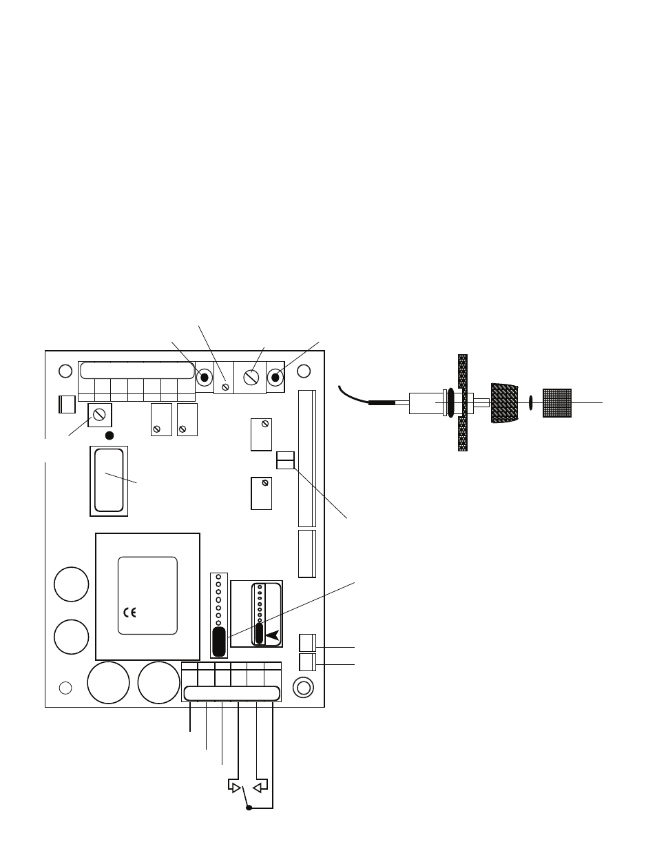
WARNING: there are two (2) O-rings installed on the switches,
one (1) on the shank and the other is under the push button. Both
of these O-rings must be reinstalled to maintain IP65/NEMA 4X
ratings. See figure III.A.3.
1-4 assumes this is a conversion from a single alarm/control.
Skip to #5 if new installation or assembly.
1. Carefully remove the RED LED from the front panel by
pulling lightly on the wires. It may be necessary to use a
small flat screwdriver to slightly spread the retaining
ring.
2. Remove the set point switch from the front panel by
rotating the round bezel nut CCW on the front panel, see
figure III.A.4.
3. Remove the LOWER front label.
4. Clean off remaining adhesive, if possible with alcohol.
5. Install DUAL alarm LOWER label, P# L2ALARM.
6. Install the SCO Second Alarm/Control RED LED in the
UPPER position as shown in figures III.A.5 & III.A.6.
7. Install the SCO Second Alarm/Control Set Point Switch
in the UPPER center position.
8. Re-install #1 (original) Set Point Switch in the LOWER
center position.
9. Re-install the #1 (original) RED LED in the LOWER
position.
10. The GREEN LED stays in the same location.
a. Set Point Conversion (SPC) /
Reversing Set Point
The alarm/control circuit(s) on all 720 Series II pH and ORP
Monitor/controllers are configured to trigger the alarm relay as the
reading increases.
If the user’s application requires it, the alarm/control circuit may
be easily reconfigured to trigger the alarm/control relay as the pH
(or ORP) reading decreases. Refer to figure III.A.4 for the
locations of the SPC jumpers referred to in this section.
20
Figure III.A.2
SET POINT #1
CONVERSION
FUSE*
115/
230
TRANSFORMER
RELAY #1
}
COM
{
POWER
AC LINE/ +DC
AC NEUTRAL/ -DC
GROUND
NC
NO
SOLID STATE (24VDC 30mA) OUTPUT
PA™ PIEZO ELECTRIC ALARM OR
RA™ REMOTE ALARM OR
CUSTOMER CONNECTION
PA
REMOVE JUMPER TO INSTALL SC/SCO
SECOND ALARM/CONTROL MODULE
721 726
722 727
723 728
724 729
MYRON L
COMPANY
UP
}
3S
INC
SPC
CONFIGURATION
MODULE
SPAN
ZERO
HYS1
SP1
ZERO
DO NOT
ADJUST
pH
SET POINT #1 (high)
ADJUST
SET POINT #1
HYSTERESIS
RIGHT INC
LEFT DEC
7 pH/ZERO mV
PUSH TO TEST
SPAN (GAIN )
PUSH TO TEST
DIS
ORP ZERO
PWR
C GD NC NO CM
SP
AN
DEC
GND
CHS
RA
PA
RE
MO
VE
T
O
SE
CO
ND
R
EL
AY
IN
ST
AL
L
pH
}
BK WT RD GN NU R- R+
SWITCH
FRONT PANEL
BEZEL
PUSH
BUTTON
O-RING
O-RING
Switch / O-ring Assembly
Figure III.A.3