Dvm self - powered nc remote - powered – Myron L 729II User Manual
Page 29
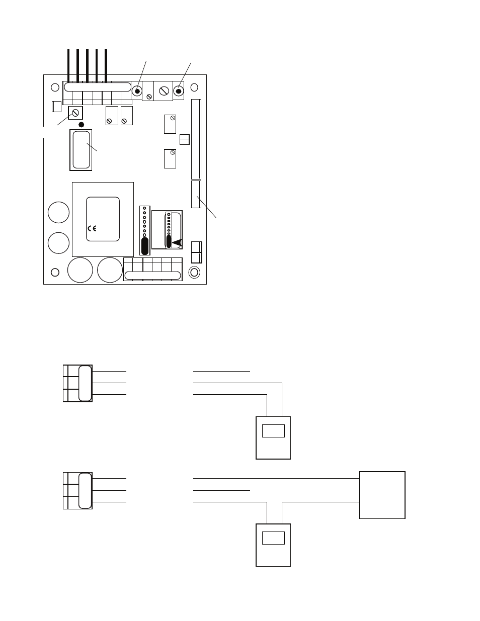
requirements, i.e. self-powered or remote-powered, see
figure III.B.5.
3. Turn power ON
4. Press the SPAN (GAIN) Test Switch with the front panel
display at 0 pH (-1999 mV for ORP) the DVM should
indicate 4 milliamps.
5. If not, adjust the cal control marked “4mA” until the DVM
indicates 4mA, see figure III.B.3.
6. Press the ZERO Test Switch, with the display indicating
7 pH (0 mV for ORP) the DVM should indicate 12
milliamps.
7. If not, adjust the cal control marked “20mA” until the
DVM indicates 12mA. See figure III.B.3.
8. Calibration is complete.
9. Turn power OFF.
10. Reconnect sensor wires to sensor terminal block as
shown in figure III.B.4.
11. Carefully reinstall the front panel, bottom first, ensure no
wires have been pinched between enclosure and front
panel.
12. Reinstall the screws and tighten.
13. To operate, turn power ON.
25
Figure III.B.4
INC
DIS
ORP ZERO
CHS
GND
REMOVE TO
INSTALL
FUSE*
115/
230
TRANSFORMER
0-10VDC
MAIN CIRCUIT BOARD ASSEMBLY
721 726
722 727
723 728
724 729
MYRON L
COMPANY
3S
DEC
SPC
CONFIGURATION
MODULE
SPAN
ZERO
HYS1
SP1
SPAN
ZERO
DO NOT
ADJUST
7 pH/ZERO mV
PUSH TO TEST
SPAN (GAIN)
PUSH TO TEST
UP
}
ORP
4-20
CONNECTOR
CONNECT 4AO
HARNESS HERE
SENSOR
ORP
}
PWR
C GD NC NO CM
CHS
GND
RE
MO
VE
T
O
SE
CO
ND
R
EL
AY
IN
ST
AL
L
DEC
SP
AN
BK WT RD GN NU R- R+
PA
RA
(+)
(-)
+
-
(+)
SIGNAL OUT
POWER OUT
POWER IN
+
DVM
Self - Powered
NC
Remote - Powered
(+)
(-)
+
-
(+)
SIGNAL OUT
POWER OUT
POWER IN
+
DVM
Remote
Power
Supply
NC
Figure III.B.5
SO
P
O
P
I
SO
P
O
P
I