Myron L 729II User Manual
Page 49
45
B.
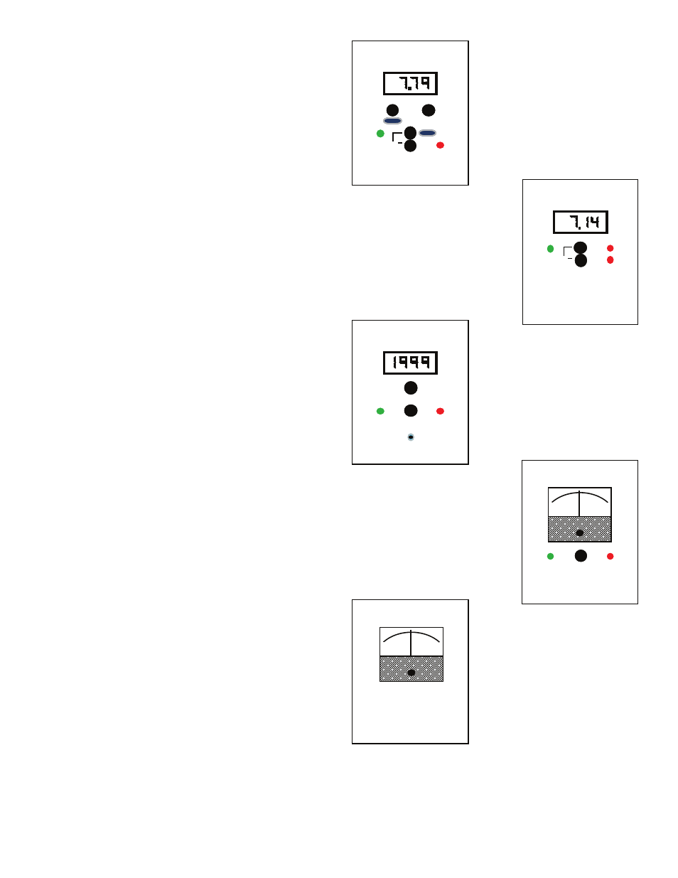
OEM FRONT PANEL INDICATORS &
CONTROLS
The simulated OEM front panel illustrations to the right, and
switch and indicator operational descriptions have been provided
to assist the OEM user in identifying and operating the 720 Series
II
Monitor/controllers.
Refer to Section V.C. for Setup procedures, and Section V.D. for
Check-Out procedures.
1. RED “HIGH SET POINT” LED INDICATOR
The red LED indicator light is ON only when the water’s pH or ORP
reading is HIGH or ABOVE the set point adjustment. May be
reversed if desired.
2. GREEN “LOW SET POINT” LED INDICATOR
The green LED indicator light is ON only when the water’s pH or
ORP reading is LOW or BELOW the set point adjustment. May be
reversed if desired.
3. “SET POINT” SWITCH(ES)
When the “SET POINT” switch is depressed, the internal set point
reading is immediately displayed on the front panel display. See
figures IV.B.1 thru 4.
4. ANALOG METER OR DIGITAL DISPLAY
Panel mounted analog meter or digital display provide a
continuous readout of the water being monitored.
pH Models 721II & 722II and ORP Models 726II & 727II are
equipped with analog meter only as shown in figures IV.B.4 & 5.
pH Models 723II & 724II and ORP Models 728II & 729II are
equipped with a 3 1/2 digit, 1/2” Liquid Crystal Digital Display, as
shown in figures IV.B.1 thru 3., with a 3 1/2 digit backlit LCD as an
option.
5. OPTIONAL PANEL MOUNTED ITEMS
TP/TPO Module Switch
A digital Monitor/controller with the optional TP/TPO Temperature
Module has an additional switch on the front panel as shown in
figure IV.B.1.. This push-button momentary switch when pushed
gives the user a direct reading of the temperature of the solution
from 0-200°C. Additional option TH/THO includes a control
function capability. See figure IV.B.1.
7pH or ZEROmV Test Switch (TEST)
This optional feature allows the user to see the ZERO TEST value
without opening the panel to push the internal switch. See figures
IV.B.1 and IV.B.3 for typical examples.
Piezo Alarm
Audible alarm sounds off automatically when the set point is
reached. Mounted by OEM in any convenient location as shown in
figure IV.B.3.
WARNING: THE DISPLAY WILL BE IRREPARABLY
DAMAGED IF THE HARNESS IS INSTALLED UPSIDE-
DOWN. THE HARNESS MUST BE INSTALLED AS
SHOWN IN FIGURE II.E.3.
HIGH
LOW
SET POINT
HIGH
LOW
SET POINT
LOW
SET POINT
TEMPERATURE
TEMPERATURE
TEST
Figure IV.B.1
Figure IV.B.2
Figure IV.B.3
Figure IV.B.4
Figure IV.B.5
HIGH
LOW
SET POINT
TEST
NOTE: Boxes around displays
to simulate OEM panels.
0
14
12
6
2
8 10
4
pH
ORP
2
2
1.5
.5
1.5
.5 1
1
0
X1000
Analog pH
Monitor/controller
(Single Alarm/control)
Digital pH
Monitor/controller
with optional Dual
Alarm/controls
Digital ORP
Monitor/controller with
optional Front Panel
Test Switch, Single
Alarm/control, and
Piezo Alarm.
Analog
ORP
Monitor
Digital pH
Monitor/controller
with optional
Dual Alarm/controls,
and Temperature with
control function, and
Front Panel Test Switch.
726II
722II
728II-PTS-PA
723II-SC
723II-SC-TP-THH-PTS