Myron L 729II User Manual
Page 28
FATAL
TO
PERSONNEL.
ONLY
QUALIFIED
PERSONNEL
SHOULD
INSTALL
ELECTRICAL
EQUIPMENT.
Physical
If the front panel has all ready been removed from the enclosure
skip to #3.
1. Using a standard slot screwdriver remove the
screws on the front panel.
2. Carefully wiggle the front panel to loosen the gasket and
pull gently toward you. Do not pull more than about 8
inches/20CM or you could damage the wiring harness.
3. Turn the front panel around so that the back side is
facing you.
4. Using a standard slot screwdriver remove the four (4)
screws holding the plastic display retainer plate to the
front panel. When the screws have been removed, the
plastic display retainer plate and the display will be free
from the front panel.
5. Set front panel down or carefully allow to hang from the
harness. Do not drop as the harness connector will pull
out allowing the front panel to fall.
6. While holding the display and the plastic display retainer
plate, carefully remove the display harness connector.
Do not drop the display. Remove and discard the plastic
display retainer plate.
7. While still holding the display in the palm of your hand,
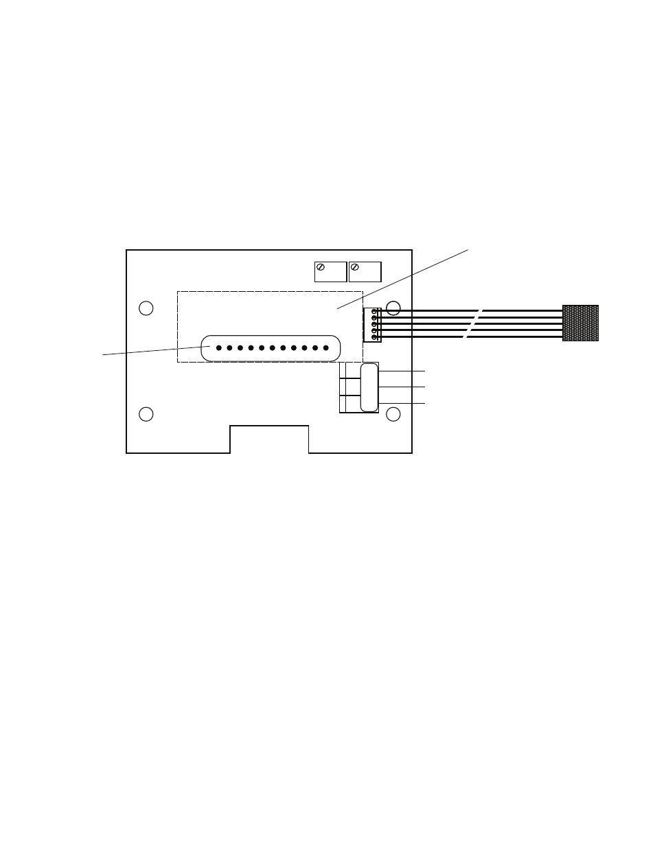
set the 4-20 Module over it with the display pins
protruding through the center opening as shown in figure
III.B.3.
8. Reconnect the harness to the display as shown in figure
III.B.3.
9. While holding the front panel, align the display to the
opening while at the same time align the 4-20 Module
mounting holes to the front panel.
10. Reinstall the four (4) screws and tighten.
Electrical
1. Connect the 4-20 Module (five) 5 wire harness to the
main circuit board at the location next to the display
harness marked “4-20” as shown in figure III.B.4.
2. Connect the signal and power wires as required, as
shown in figures III.B.1. & III.B.2. This assumes you
have already connected the other end of the wires as
required.
a. Place the remote interface cable and user supplied
watertight cable restraint into the enclosure’s
appropriate access hole.
b. Neatly connect the signal cable wires to the
Monitor’s appropriate connectors as shown in figure
III.B.3.
3. To test, turn power ON.
4. Press the SPAN switch located on the main circuit
board, see figure III.B.4, and monitor the output at your
remote site, display should indicate 0 (pH) or -2000 mV
ORP); With a DVM connected and set to DC milliamps,
see figures III.B.1. & III.B.2, DVM should indicate 4mA.
5. Press the ZERO switch located on the main circuit
board, see figure III.B.4, and monitor the output at your
remote site, display should indicate 7 (pH) or 0 mV
(ORP); With a DVM connected and set to DC milliamps,
see figures III.B.1. & III.B.2, DVM should indicate
12mA.
5. Turn power OFF.
6. Carefully reinstall the front panel, bottom first, ensure no
wires have been pinched between enclosure and front
panel.
7. Reinstall the screws and tighten.
8. To operate, turn power ON.
3. RECALIBRATION
The 4-20 Module was calibrated at the factory, however, if you
wish to check the calibration the following procedure will help you
to accomplish this task. Exercise caution while performing this
procedure.
Requirements; a DVM set to DC milliamps, a tweaker or small
standard slot screwdriver.
This procedure assumes the front panel is removed.
1. If sensor is connected, disconnect sensor wires from
sensor terminal block.
2. Attach the DVM to the output connectors per your
24
Figure III.B.3
TO TO MAIN CIRCUIT BOARD
4
20
DISPLAY
4A/4AO - 4-20mA MODULE
4-20
(+)
(-)
+
-
(+)
SIGNAL OUT
POWER OUT
POWER IN
+
DISPLAY IS ON BACK SIDE OF 4-20 MODULE
RECONNECT
DISPLAY
CONNECTOR
HERE
SO
P
O
P
I