Myron L 729II User Manual
Page 22
8. Reverse the above procedure using the new scale.
NOTE: While replacing the clear plastic cover, ensure the
ZA screw pin on the cover aligns with the inverted “Y” shaped
slot on the meter movement. See figure II.G.5.
IF, the inverted “Y” shaped slot is inadvertently moved -
BEFORE installing cover:
a. Recenter the inverted “Y” to the meter case as
shown in figure II.G.5.
b. Center the Zero Adjust (ZA) PIN on the clear
plastic cover as shown in figure II.G.6.
9. Using a standard slot screwdriver, ensure the ZA is
operating - pointer swings left and right when turning the
ZA with a standard slot screwdriver. See figure II.G.7.
10. Set Meter ZERO as shown in figure II.G.7.
11. Reinstall meter to front panel, reversing steps 1-3
(except OEM models).
REASSEMBLY
1. Carefully reinstall the front panel, bottom first, ensure no
wires have been pinched.
2. Reinstall the screws and tighten.
3. To operate, turn power ON.
18
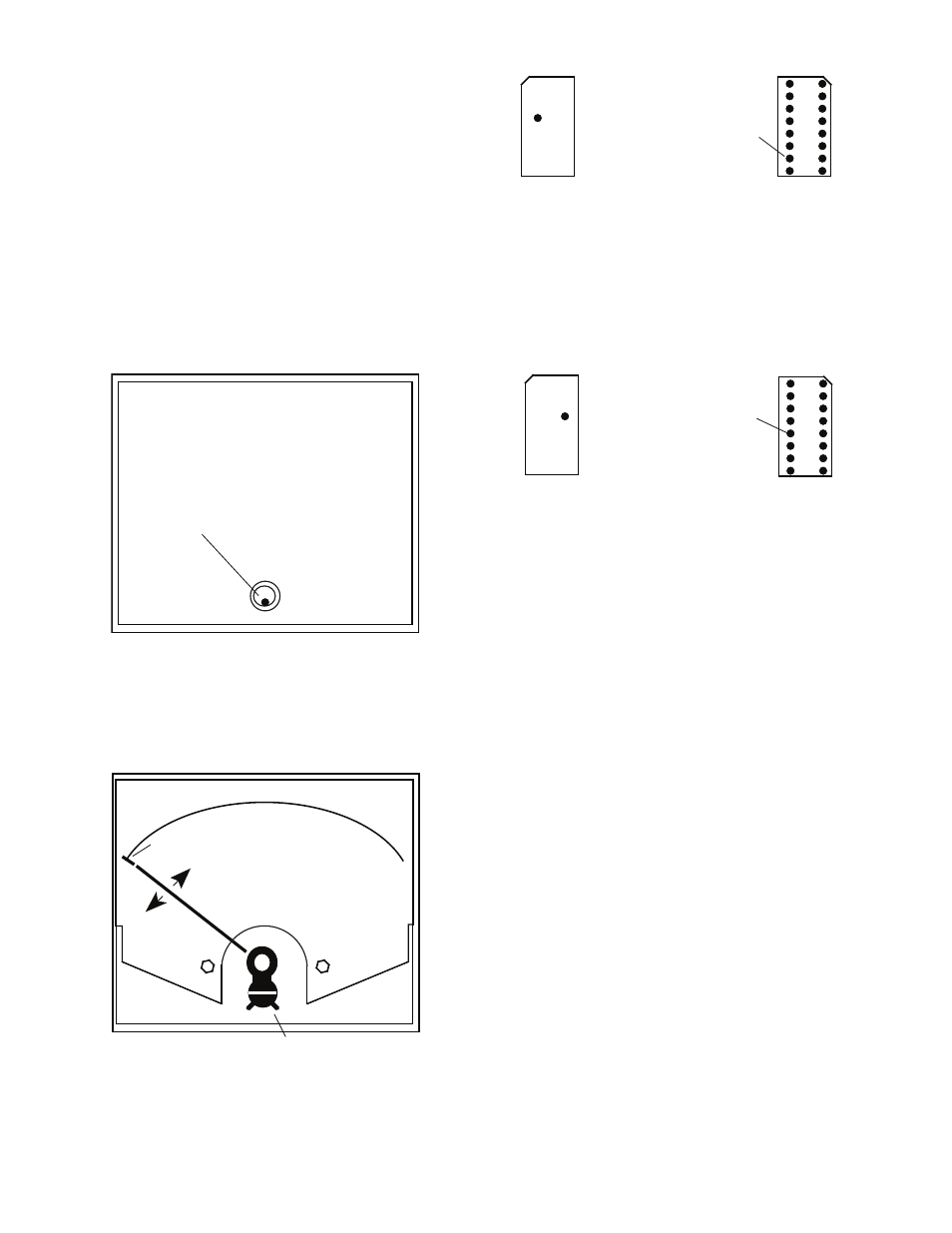
Figure II.G.6
CLEAR PLASTIC COVER
(Inside View)
CENTER Zero Adjust (ZA) PIN
Figure II.G.7
Zero Adjust (ZA)
CLEAR PLASTIC COVER
(case not shown for clarity)
0
Align Pointer with FIRST Line
Figure II.G.8
UP
PIN #10
ANALOG
REMOVED
Bottom View
ORP
CONFIGURATION
MODULE
UP
Top View
}
ORPD O
ORP
A O
“ANALOG”
Figure II.G.9
UP
PIN #12
DIGITAL
REMOVED
Bottom View
ORP "DIGITAL"
CONFIGURATION
MODULE
UP
Top View
ORP
A O
ORPD O
}