Myron L 729II User Manual
Page 38
D.
ALARM/CONTROL KIT
(Digital & OEM Models only)
-TH
Controller wiring Harness (requires second alarm/control
module) ordered with Monitor/controller.
THO Controller wiring Harness (requires second alarm/control
module) ordered separately.
1. DESCRIPTION
The optional TH/THO Controller Kit adds more flexibility to
the Temperature Module by adding the ability to Alarm and/or Control
using the 24VDC solid state output to drive a PA - Piezo electric
alarm, and/or a 10 amp relay to operate a heater or chiller as
required.
Kit includes
THO kit comes with all items necessary to install and operate:
Alarm/control Harness (replaces second alarm/control relay
harness) with switch, bezel, cap and two O-rings (006 & 008); and
TEMPERATURE label (# LTEMP).
Requirements
-SC/SCO Alarm/Control Module (#2 set point/relay) option
-TP/TPO Temperature Module option
The TH/THO uses SC/SCO Second alarm/control Module on Main
circuit board [Conductivity/TDS, Resistivity, pH or mV (ORP)].
2. INSTALLATION
Briefly -
The SCH (switch and LED) harness is removed from the SC and
front panel, and discarded.
The THO harness is installed to the SC, TPO or other controllable
option, and front panel.
A label is installed on the front panel.
WARNING: BEFORE STARTING, IF MONITOR/
CONTROLLER IS INSTALLED, ENSURE THE POWER
IS OFF. FAILURE TO DO SO COULD CAUSE DAMAGE
TO THE INSTRUMENT, AND COULD BE HARMFUL OR
FATAL
TO
PERSONNEL.
ONLY
QUALIFIED
PERSONNEL
SHOULD
INSTALL
OR
SERVICE
ELECTRICAL EQUIPMENT.
Physical
First, you must decide which location to install the THO harness
LED and Set Point switch. This is easily determined by how the
Primary or the Main CB Alarm/control is used. If the Primary
Alarm/control is used as a HIGH control, as in Conductivity, than
the THO harness is installed in the lower location - see section
III.D.2.a., this page, top of the next column.
If your Primary or Main circuit board Alarm/control is used as a
LOW control, as in Resistivity, than the THO harness is installed
in the HIGH location — see section III.D.2.b, page 35, halfway
down the second column.
WARNING: Before installing switch keep in mind there are two
(2) O-rings installed on each switch, one (1) on the threaded
shank and the other is under the push button. Both of these must
be reinstalled properly to maintain IP65/NEMA 4X ratings, see
figure III.D.4.
a. HIGH Primary Control
If the front panel has all ready been removed from the enclosure
skip to step 3.
1. Using a standard slot screwdriver remove the
screws on the front panel.
2. Carefully wiggle the front panel to loosen the gasket and
pull gently toward you. Do not pull more than about 8
inches/20CM or you could damage the wiring harness.
3. Remove SCH harness from front panel and SC/SCO
Second Alarm/Control Module.
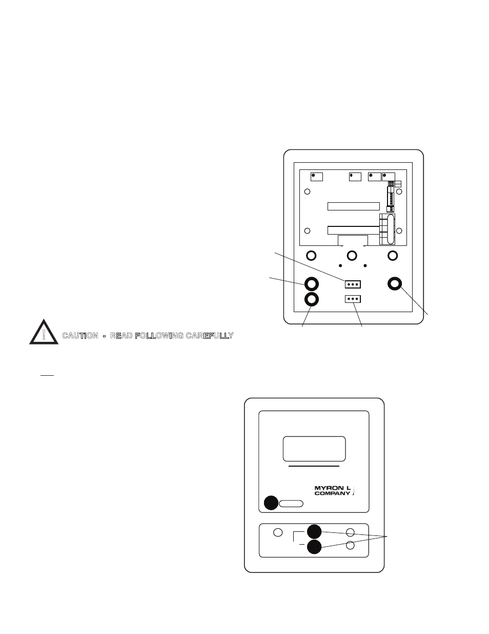
a. Carefully remove the RED LED from the front panel
34
FRONT PANEL
Rear View
REMOVE
PRIMARY
RED LED
REMOVE
PRIMARY SET
POINT SWITCH
Green
LED
LOW
REMOVE
SC/SCO
SET POINT
SWITCH
and
RED LED
FS
ZERO
DIS
SP2
HYS2
DISPLAY CONNECTION
DISPLAY
SELECT
TEMP
CONTROL
HARNESS
DISPLAY
BRN
BLU
+
0-5VD
-
INC
INC
TEMP
SENSOR
TP/TPO - TEMPERATURE MODULE
DEC DEC
BR
B
L
O
R
-
+
SPC
Figure III.D.1
!
CAUTION - READ FOLLOWING CAREFULLY
720
II
HIGH
LOW
SET POINT
FRONT PANEL
Figure III.D.2
ROUND
BEZEL
NUTS
TEMPERATURE
pH