Myron L 729II User Manual
Page 46
42
G. REMOTE ALARM - RA™
RA
Ordered as an accessory, includes 8” harness with
connector, and two (2) wire nuts.
1. DESCRIPTION
This remotely mounted AUDIBLE and VISUAL alarm connects to
any Myron L Company Monitor/controller, or brand “X” controller
with dry contacts. When activated by the controller the Remote
Alarm will provide both an audible and a visual alert at a location
other than at the controller.
A mute button will silence the piezo alarm for up to 10 minutes
while the LED remains illuminated. After the preset time the piezo
alarm will again sound, this will repeat until the water quality is
corrected. Thus allowing servicing of the system under control,
while still acting as a reminder if the problem has not been
corrected.
The Remote Alarm - RA™ is an inexpensive way to alert personnel
of a trouble situation. For example; the Monitor/controller may be
located with an RO system while the service technicians are on
another floor or even in another building - great for hospitals. The
AUDIBLE alarm may be silenced, but stays in alarm (RED LED is
still illuminated) until the trouble is corrected. The timer may be
set from 15 seconds up to 10 minutes, thereby, giving personnel
the time to correct the problem while not being able to ignore the
trouble because of the reoccurring AUDIBLE and VISUAL alerts.
Specifications
Audible Alert — Piezo Electric
Oscillating Frequency — 3.0±0.5KHz
Operating Voltage (720II) — 24VDC Nom. (1.5-30VDC Max.)
Sound Pressure Level (Min) 30cm/12VDC — 80dB
Current consumption (Max) @ 12VDC — 12mA
Tone — Constant
Operating Temperature — -20 - +60°C
Size — 24 x 9.5 mm
Visual Alert — Bright RED LED
Time Delay — 15 seconds to 10 minutes (USER adjustable)
Power — 24VDC (supplied from Monitor/controller)
Case Material — ABS plastic
Dimensions — 4.75L x 2.56W x 1.56H (121L x 65W x 40H)
Mounting — Double Backed Tape (supplied)
Operational Distance — Wire lengths of 500 feet (152 meters)
have been tested with no adverse effects
Additional Wire available, order RAW-200. — 200 feet (61 meters)
2. INSTALLATION
Briefly —
Only 2 wires to connect from the controller to the RA.
Set the time.
Mount on the wall or on the bench.
WARNING: BEFORE STARTING, IF MONITOR/
CONTROLLER IS INSTALLED, ENSURE THE POWER
IS OFF. FAILURE TO DO SO COULD CAUSE DAMAGE
TO THE INSTRUMENT, AND COULD BE HARMFUL OR
FATAL
TO
PERSONNEL.
ONLY
QUALIFIED
PERSONNEL
SHOULD
INSTALL
ELECTRICAL
EQUIPMENT.
The Remote Alarm - RA connector is labeled 24VDC INPUT and
has a 8” 2 conductor wires attached — Black is Positive (+) and
White is Negative (-).
When extending the wires you may use any two color wire you
wish just remember the polarity — Black is Positive (+) and White
is Negative (-). Wire lengths of 500 feet/152 meters have been
tested and have no adverse effect on performance although a
length of 500 feet/152 meters would be unusually long.
Ensure the unit is completely wired, tested and adjusted before
installing RA to mounting surface as the tape will not remove from
mounting surface without damaging the adhesive.
For OEM models skip steps referencing enclosure or front panel.
1. Run #22, 2 conductor speaker type wire, NOT supplied,
from Monitor/controller to RA location as necessary. Wire
may be ordered from the Myron L Company, part #RAW-
200.
2. Open the RA by removing the four screws.
3. Locate and remove the 8” 2 conductor wire with the
reddish brown connector attached to the RA. See figure
III.J.1.
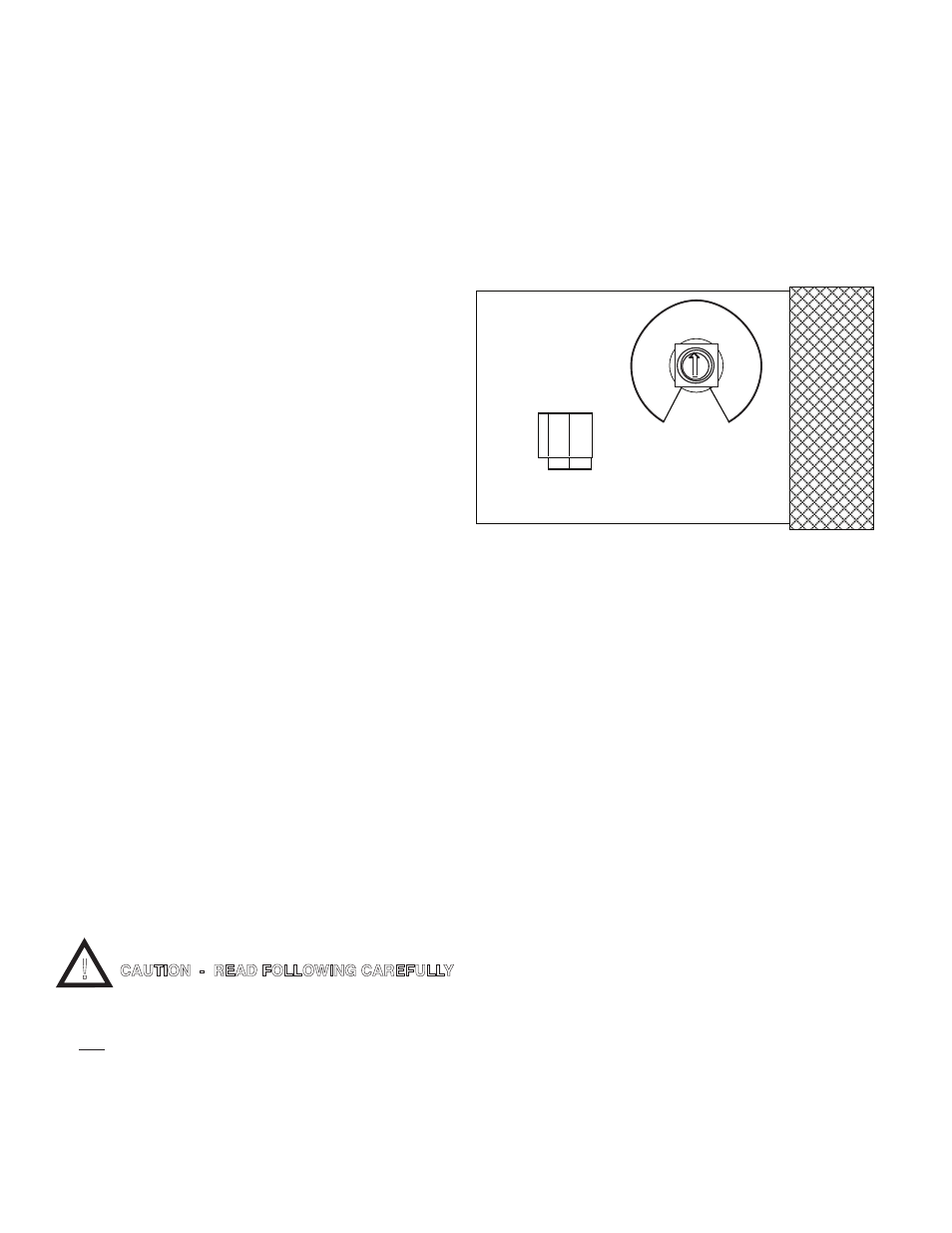
4. At the RA, connect the extension wires to the connector
on the RA circuit board — Black to Positive (+) and White
to Negative (-) as shown in figure III.G.1.
5. Using a standard slot screwdriver remove the
screws on the Myron L Monitor/controller front panel.
6. Carefully wiggle the front panel to loosen the gasket and
pull gently toward you. Do not pull more than about 8
inches/20CM or you could damage the wiring harness.
7. Connect the extension wires to the 8” 2 conductor wire
with the wire nuts provided — Black to Positive (+) and
White to Negative (-). Be sure to first pass the wire
through the user supplied waterproof strain relief in the
enclosure.
8. Plug the reddish brown connector into the male
connector on the controller circuit board marked RA (see
inside case label or figure III.J.2 for location). It will only
go on the connector one way.
9. To test, simply turn ON the controller and adjust
controller set point until the alarm sounds off*.
The black button on the front of the RA will mute the piezo
alarm for approximately three minutes or until you
improve the water quality (readjust controller set point). If
three minutes muting is fine for your application, skip to
#10.
!
CAUTION - READ FOLLOWING CAREFULLY
RA CB ASSEMBLY
CONTROLLER
+ -
10
4
15
30
7
8
5
9
3
2
1
6
MIN
SEC
Figure III.G.1