Recommendations for the installation, Over-temperature protection, Operation – NOVUS N1540 Process Indicator User Manual
Page 3: Description of the parameters
N1540 Indicator
NOVUS AUTOMATION
3/5
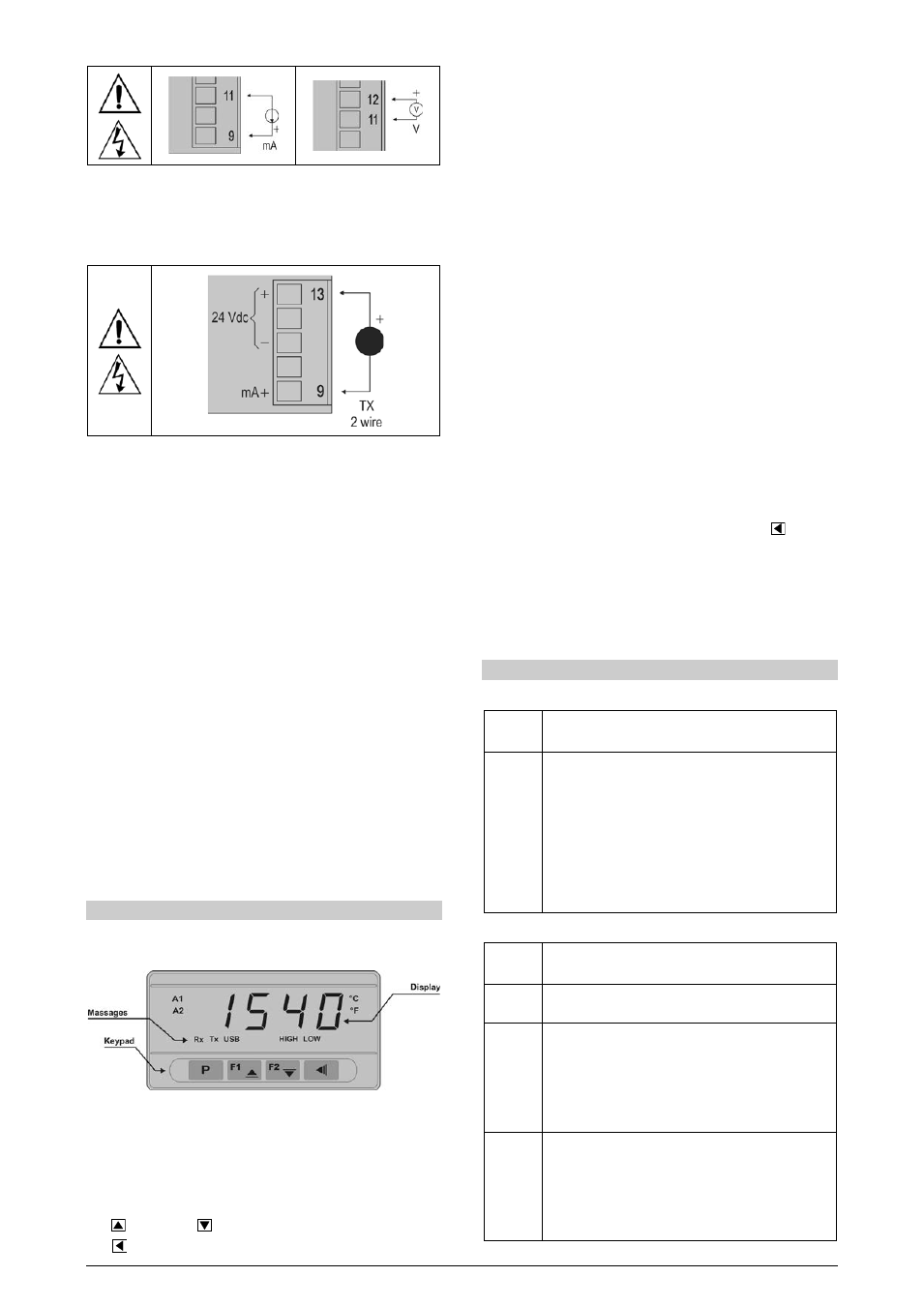
Figure 03 – Current (mA) and Voltage (V) signal connection
This indicator offers an auxiliary 24 Vdc power supply which is
tipically applied to power up two wire 4-20 mA field transmitters. The
Figure 04 presents the wiring for this application.
Figure 04 – Auxiliary 24 Vdc usage example
RECOMMENDATIONS FOR THE INSTALLATION
• To minimize the pick-up of electrical noise, the low voltage DC
connections and the sensor input wiring should be routed away
from high-current power conductors. If this is impractical, use
shielded cables. In general, keep cable lengths to a minimum.
• The input signals conductors shall be positioned throughout the
factory separate from the output and the power supply
conductors, in grounded conduits if possible.
• The power supply of the electronic instruments shall come from a
proper source for the instrumentation network.
• It is recommended to use RC FILTERS (0,1 uF in series with 100
ohms) to suppress the noise generated by contactors coils,
solenoids, etc.
OVER-TEMPERATURE PROTECTION
When designing any control system it is essential to consider what
will happen if any part of the system should fail. In temperature
control applications the primary danger is one in which the heating
remains constantly on. In any application where physical injury or
destruction of equipment might occur, it is recommend to install an
independent protection equipment, with a separate temperature
sensor, to disable the heating circuit in case of overheating. Please
note that the alarm relays within the indicator will not give protection
under all failure conditions.
OPERATION
The indicator front panel, together with its elements, can be seen on
Figure 02:
Figure 02 - Identification of the front panel parts
Display: Shows the process variable PV, the configuration
parameters prompts and their respective values/conditions.
Indicators A1 and A2: signalize the occurrence of an alarm
condition.
Key P: used to walk through the parameters in the menu cycles.
F1 /
key and F2 /
key: Used to change parameter values.
Key
: go back to the previous displayed parameter.
START UP
When the indicator is powered up, its firmware version is displayed
for 3 seconds, after which the N1540 starts normal operation, when
the value of PV is displayed and the outputs are enabled.
Before the indicator is ready to be used in a given process, it requires
some basic configuration, consisting of assigning values to the
parameters according to the desired behavior. The user shall
understand the importance of each parameter and determine a valid
condition or a valid value for each one of them.
The configuration parameters are grouped in levels according to their
affinity. The 4 parameters levels are:
1 – Operation
2 – Alarms
3 – Input
4 – Calibration
The “P” key provides the access to the levels and to the parameters
of these levels.
Keeping the P key pressed, at every 2 seconds, the indicator jumps
from one level to another, presenting the first parameter of each
level:
PV >> fva1 >> type >> pass >> PV …
To enter into a particular level, simply release the P key when the
first parameter in that level is displayed.
To walk through the parameters in a level, press the P key with short
strokes. To go back to the previous parameters, use the
Key.
The display alternates the presentation of the parameter prompt and
its value. The parameter value is displayed with a light blinking to
differentiate it from the parameter prompt.
Depending on the level of parameter protection adopted, the
parameter PASS precedes the first parameter in the level where the
protection is active. See section PROTECTION CONFIGURATION.
DESCRIPTION OF THE PARAMETERS
OPERATION CYCLE
PV
Indication Display of PV. The value of the measured
variable (PV) is shown on the upper display (red).
Sp.a1
Sp.a2
Alarm SP: Value that defines the alarm activation point.
For the alarms set up with the functions of the type
Differential, these parameters define the maximum
differences accepted between PV and a reference
value defined in the parameter ALrF.
For the alarm function ierr, this parameter is not
used.
Parameters shown in this level only when enabled in
the parameters sp1.E and sp2.E.
ALARMS CYCLE
Fva1
Fva2
Alarm Functions. It defines the functions of the alarms
among the options in Table 02.
al.rf
Reference value used by the alarms with differential
function, minimum differential or maximum differential.
Sp.a1
Sp.a2
Alarm SP: Value that defines the point of activation of
the alarm outputs. For the alarms programmed with the
functions of the type Differential, these parameters
represent the deviations.
For the ierr alarm function, this parameter has no
meaning.
Sp1.e
sp2.e
SP Enable
It allows the parameters SPA1 and SPA2 to be displays
also in the indicator operation cycle.
YES
shows the parameters SPA1/SPA2 in the
operation cycle
NO
Does not show the parameters SPA1/SPA2 in
the operation cycle