Connecting to optional components – AMX PTM-D15 User Manual
Page 16
Installation and Wiring
10
PTM-D15 15" Platinum Touch Panel
Connecting to Optional Components
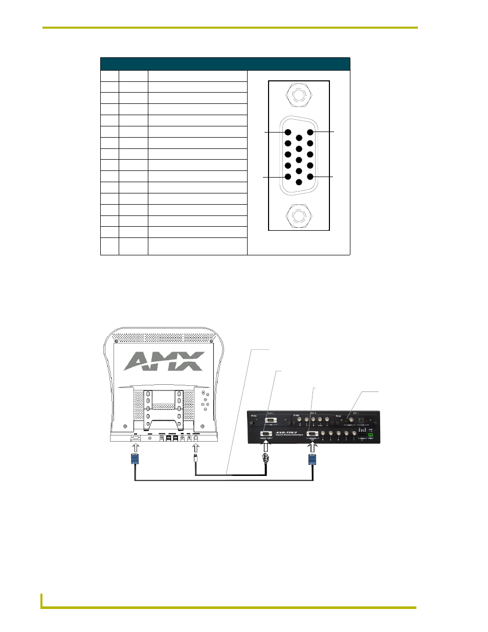
In this example, the Platinum panel is connected to a TPI/3 interface.
1.
Connect the VGA signal cable from the rear of the PTM-D15 panel to the Monitor Out port on
the back of the TPI/3 (FIG. 8).
2.
Connect the Touch Screen signal cable from the rear of the panel to the Mouse Port on the back
of the TPI/3.
3.
Connect the incoming video signal connector to either the Composite or S-Video connector
ports on the TP3-VID card.
VGA IN DB-15 Connector Pinouts
Pin Signal
Function
1
Red
Red signals
2
Green
Green signals
3
Blue
Blue signals
4
N/A
Not used
5
GND
Signal Ground
6
RAGND
Red analog ground
7
GAGND
Green analog ground
8
BAGND
Blue analog ground
9
N/A
Not used
10
SAGND
Synchronization analog ground
11
N/A
Not used
12
N/A
Not used
13
HSYNC
Horizontal synchronization signal
14
VSYNC
Vertical synchronization signal
15
N/A
Not used
FIG. 8 Attaching the cables from the panel to the rear of the AXB-TPI/3
VGA DB-15 (male)
connector
10
6
5
1
15
11
VGA Input cable - connects to
Monitor Out port on TPI/3
Touch Screen cable - connects to
Mouse Port on TPI/3
Mouse port
Connect
incoming
video to
TP3-VID
card
Monitor Out
port