HID Serial ProxPro Reader Installation Guide User Manual
Page 9
________________________________________________________________________________________________
HID Corporation 9292 Jeronimo Road Irvine, CA 92618-1905 USA TEL (949) 598-1600 (800) 237-7769 FAX (949) 598-1690
http://www.prox.com Serial ProxPro Reader Installation Manual 5352-900 Rev F 8 of 9
This method of interfacing the keypad requires additional processing by the host. These include the de-
bouncing of the keys, decoding of the keypad, timing between key entries, as well as others depending on the
Host. The 2 of 7 format is available on the Serial ProxPro 5352XXKXX versions.
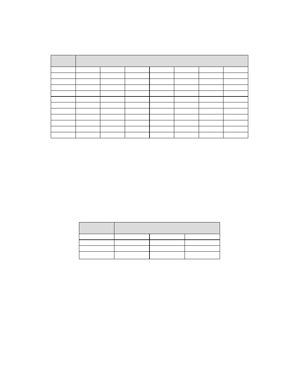
Key Pad Data Table - 2 of 7
Key #
Terminal Number
P2-1 P2-2 P2-3 P2-4 P2-5 P2-6 P2-7
1 LO HI
HI HI HI HI LO
2 LO HI
HI HI HI LO HI
3 LO HI HI HI LO HI HI
4 HI LO HI HI HI HI LO
5 HI LO HI HI HI LO HI
6 HI LO HI HI LO HI HI
7 HI HI LO HI HI HI LO
8 HI HI LO HI HI LO HI
9 HI HI LO HI LO HI HI
* HI HI HI LO HI HI LO
0 HI HI HI LO HI LO HI
# HI HI HI LO LO HI HI
HI represents a voltage of +5 volts in reference to the Serial ProxPro ground.
LO represents the Serial ProxPro ground.
Note: The Keypad/Reader is to be used on a single point ground system.
S Version - Direct connect keypad Scanning - 3 X 4 Matrix format
The Serial ProxPro reader is available with a 3 x 4 matrix keypad. The keypad is independent of the Serial
ProxPro reader and only provides the connections to the keypad. This mode requires a separate cable to be
supplied that connects to the Keypad board, inside the ProxPro, to the Host via P2. P2 is a 7 position terminal
strip. The following is the table for the contact closures.
This table indicates the connection between the connector pins when a key is pressed. For example, if key 3 is
pressed P2-5 is connected (shorted) to P2-1. This is available on the Serial ProxPro 5352XXSXX versions.
Rows
Columns
P2-5 P2-6 P2-7
P2-1
3 2 1
P2-2
6 5 4
P2-3
9 8 7
P2-4 # 0 *