HID Serial ProxPro Reader Installation Guide User Manual
Page 5
________________________________________________________________________________________________
HID Corporation 9292 Jeronimo Road Irvine, CA 92618-1905 USA TEL (949) 598-1600 (800) 237-7769 FAX (949) 598-1690
http://www.prox.com Serial ProxPro Reader Installation Manual 5352-900 Rev F 4 of 9
RS232/RS422/RS485 Card Message Specification
When Access Cards (transponders) are presented to the ProxPro reader, the reader sends a message. The
message is in the following format:
CCDDDDDDDDDDXX
^ First character sent
1. All characters C, D and X are ASCII encoded, hexadecimal digits.
(i.e. The hex value 7 is sent as an ASCII character 7 or the hex value E is sent as an ASCII character E)
2. The CC field is reserved for use by HID Corporation. The valid values are 00 through 7F.
3. The DDDDDDDDDD field is the transponders (Access Card) data. The valid values are 0000000000
through 1FFFFFFFFF (ASCII).
4. The XX field is a computed checksum. The checksum is calculated by first grouping the message data into
the pairs CC DD DD DD DD DD. Each pair of characters represents one byte of data. Then each pair of
characters is converted from ASCII to their respective hex values. At this point, the 6 bytes are added
together. The checksum is equal to the least significant 8 bits of the result.
5.
6.
7. For example, if the ProxPro reads a transponder (Access Card) that contains the value CC=00 and
DDDDDDDDDD=01234ABCDE, the reader will report the ASCII message 0001234ABCDE08
Note that each of the characters is ASCII encoded. The actual bytes (hex value) that are sent to the host
are <30><30><30><31><32><33><34><41><42><43><44><45><30><38><0D><0A>. The checksum was
computed by adding 00 + 01 + 23 + 4A + BC + DE = 208 hex. The checksum is the least significant 8 bits of
this result or 08 hex.
8. The communications settings are 9600 BAUD, 8 bits, 1 stop bit, no parity.
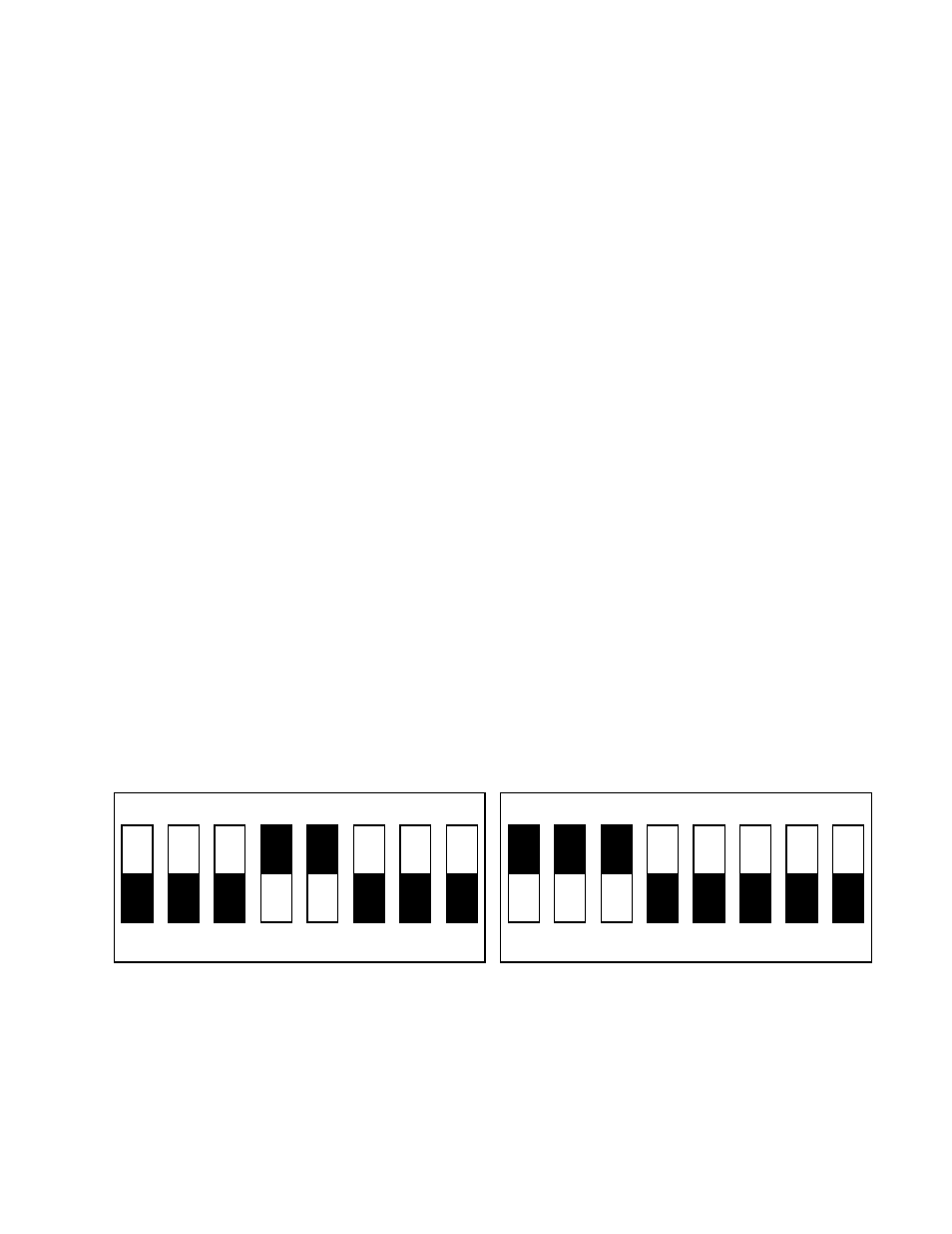
DIP Switch Settings
There are two switches on the ProxPro Serial reader that are used to select several different modes of
operation. The following is a diagram detailing the default switch settings.
1
2
3
4
5
6
7
8
on
1
2
3
4
5
6
7
8
on
SWITCH 2
SWITCH 1