Figure 1 front, side and back views – HID MIFARE Reader Installation Guide User Manual
Page 5
_________________________________________________________________________________________________
HID Corporation 9292 Jeronimo Road Irvine, CA 92618-1905 USA TEL (949)598-1600 (800)237-7769
FAX (949)598-1690 Internet - www.hidcorp.com - HID Mifare Reader Installation Manual 6055-910 Rev B Page 4 of 5
24 AWG Enamel Wire
White/Red 22AWG lead wire, 12”
White/Black 22AWG lead wire, 12”
• *Fair-Rite Prod.Corp. www.fair-rite.com
Instructions:
• Form a coil by wrapping 39 turns of a pair of
enamel wires around the toroid (see Figure 3).
• Attach Red and Black wires to one end of the coil.
• Attach White/Red wire to the opposite end of the
coil wire connected to the Red wire.
• Attach the White/Black wire to the opposite end of
the coil wire connected to the Black wire.
• Connect the red lead to the + side of the power
supply output.
• Connect the black lead to the – side of the power
supply output.
• Connect the White/Red lead to the Red wire from
the reader.
• Connect the White/Black lead to the Black wire
from the reader.
• Install the ferrite clamp on the cable, which
supplies AC line voltage to the power supply.
When installing the clamp-on ferrite part, three
loops should be formed in the power cable
between the 220 VAC source and the power
supply so that the ferrite clamp is clamped over 4
wires.
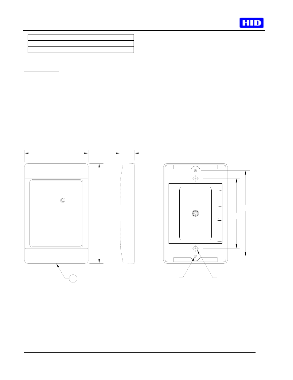
3.000
4.700
.68
7
3.280
4.020
.15 X .16
SLOT
.125
Figure 1 Front, Side and Back Views