1 parts list, 2 mounting instructions, 3 connecting the reader – HID MIFARE Reader Installation Guide User Manual
Page 3: 4 testing and operation, 5 card compatibility
_________________________________________________________________________________________________
HID Corporation 9292 Jeronimo Road Irvine, CA 92618-1905 USA TEL (949)598-1600 (800)237-7769
FAX (949)598-1690 Internet - www.hidcorp.com - HID Mifare Reader Installation Manual 6055-910 Rev B Page 2 of 5
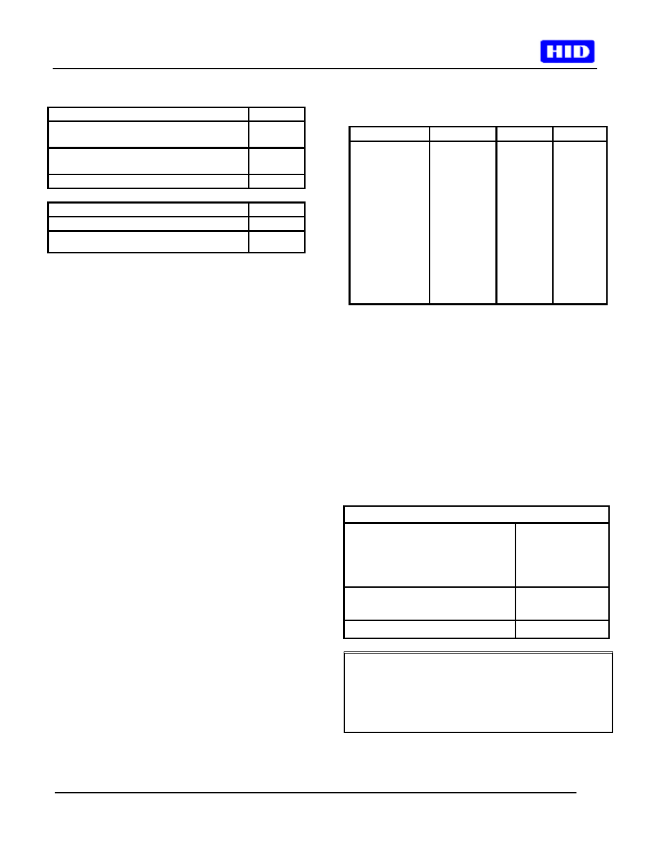
1 Parts
List
PARTS LIST (Included)
Quantity
- HID MIFARE Reader with snap-on
cover and 18in.
1
- #6-32 x 1” self-tapping panhead
screw
2
- Installation manual
1
PARTS LIST (Not-Included)
Quantity
- Wire splice
9
- DC Power supply 12 VDC
1
2 Mounting
Instructions
• Determine an appropriate mounting location. The
reader may be mounted to any surface, including
metal.
•
Drill two (2) 3/32-inch (2.5mm) holes
approximately 1 inch deep for mounting the
reader.
• Drill a 5/8-inch (16mm) hole for the cable.
• A single-gang (2S) electrical junction box may
also be used; reader fits US hole pattern, and the
6-32 screws work with the J-box.
• Remove the snap-on cover from the reader and
secure the reader to the mounting surface.
• Route the cable from the reader and/or power
supply to the host. A linear type power supply is
recommended. Check all electrical codes for
proper cable installation.
• For the cable connection to the panel - use Alpha
#1299C or equivalent.
• Test the operation of the reader (Section 4). After
completion of the test, replace the snap-on cover.
• See Figure 1 for product and mounting
dimensions.
• For proper regulatory compliance, the drain wire
should be disconnected at the power supply end
of the cable.
• Changes or modifications not expressly approved
by the party responsible for compliance could
void the user’s authority to operate the
equipment.
• The Reader is intended to be powered from a
limited power source output of a previously
certified power supply.
3 Connecting the Reader
• Connect the reader to the host according to the
wiring table below and the host installation guide.
Signal
Color
DB9F
DB25F
9-14 VDC
Red
-
-
GND
Black
Pin 5
Pin 7
D0
Green
-
-
D1
White
-
-
GRN LED
Orange
-
-
RED LED
Brown
-
-
Beeper
HOLD
Not Used
RX
DTR
TX
SHLD GND
Yellow
Blue
Violet
Pink
Gray
Tan
Drain
-
Pin 1
-
Pin 2
Pin 4
Pin 3
-
-
Pin 8
-
Pin 3
Pin 20
Pin 2
-
4 Testing and Operation
• When power is applied to the reader the beeper
will beep and flash the LED green three times.
• Present an ID card to the reader. The LED will
momentarily turn green while the beeper beeps
once, indicating that the card was read
successfully.
• Please note that typical read range for MIFARE
cards is .75 to 1.5” (20 – 37 mm).
Important Product Specifications
Power supply
Absolute Maximum Voltage
Maximum Current at 12V
Operating Voltage Range
Linear type
16 VDC
50mA
9.0 – 14.0 VDC
Maximum cable distance
To host
50 ft RS-232
500 ft Wiegand
Operating temperature range -30 to 65
°C
FCC Compliance Statement: This device complies
with part 15 of the FCC rules. Operation is subject to
the following two conditions: (1) this device may not
cause harmful interference, and (2) this device must
accept any interference received, including
interference that may cause undesired operation.
5 Card
Compatibility