Step 4 - select power scheme, Edge evo hi-o networked controller – HID EDGE EVO Solo ESH400 Hi-O Controller Installation Guide User Manual
Page 5
82000-920, D.1
INSTALLATION GUIDE
5
©2009 - 2012 HID Global Corporation. All rights reserved.
EDGE EVO Hi-O Networked Controller
EH400
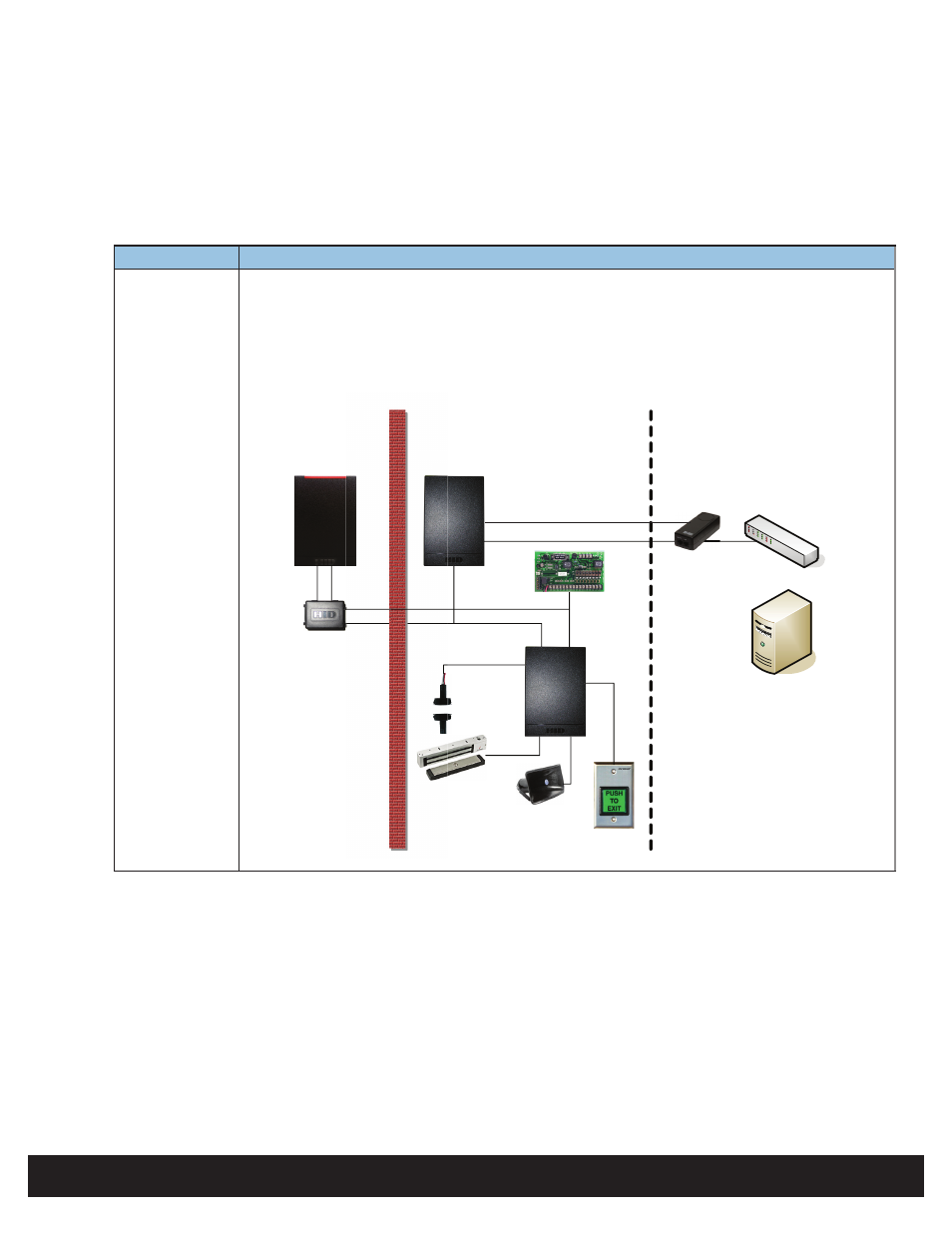
Step 4 - Select Power Scheme
Select the appropriate power scheme to meet overall current draw. Using the analysis from the previous sections equates to the
following power scheme possibilities.
Power Scheme Details
1
Hi-O CANbus power derived from an external +12VDC or +24VDC power supply. The Hi-O Networked
Controller power is derived from PoE.
•
Hi-O CANbus connections to the Hi-O Networked Controller shall omit the CANbus V+ and
CANbus GND output connections.
•
Insert a voltage converter module between the CANBus and Hi-O iCLASS reader.
•
Insert a UL294 Listed PoE Injector in the Ethernet line to power the Hi-O Networked Controller.
Unprotected
Area
Protected Area
Physical Access
Control Server
(real-time functions
not required )
Remote Area
CANbus Data
Ethernet Switch
Ethernet Data
Door Position
Switch
Magnetic Lock
REX Switch
Hi-O iCLASS
Reader
Door
Module
Local Sounder
Exit Alarm
Hi-O Networked
Controller
Magne
ted
SS
Hi-O N
Con
12 - 24VDC
Power Supply
Voltage Module
UL294 PoE
Injector
Ethernet Power