Iclass – HID bioCLASS Installation Guide User Manual
Page 6
iCLASS
RKL55, RKLB57
RWKL550, RWKLB575, bio500
INSTALLATION GUIDE
6
©2009 HID Global Corporation. All rights reserved.
6307-901 B.1
*
Le conducteur de drainage peut être une ligne de « renvoi de données » lors de l’utilisation d’une alimentation séparée.
**
Nécessite les modules d’extension [RS232, RS485, USB, UART à UART].
GPIO est l’acronyme de « General Purpose Input/Output », c’est-à-dire entrée/sortie à usage général.
***
Sortie autoprotection. Lorsqu'elle est activée, la sortie est tirée vers la masse (par défaut).
**** Selon la configuration du lecteur.
Pour plus d’informations, voir les configurations HTOG Wiegand et Clock-and-Data.
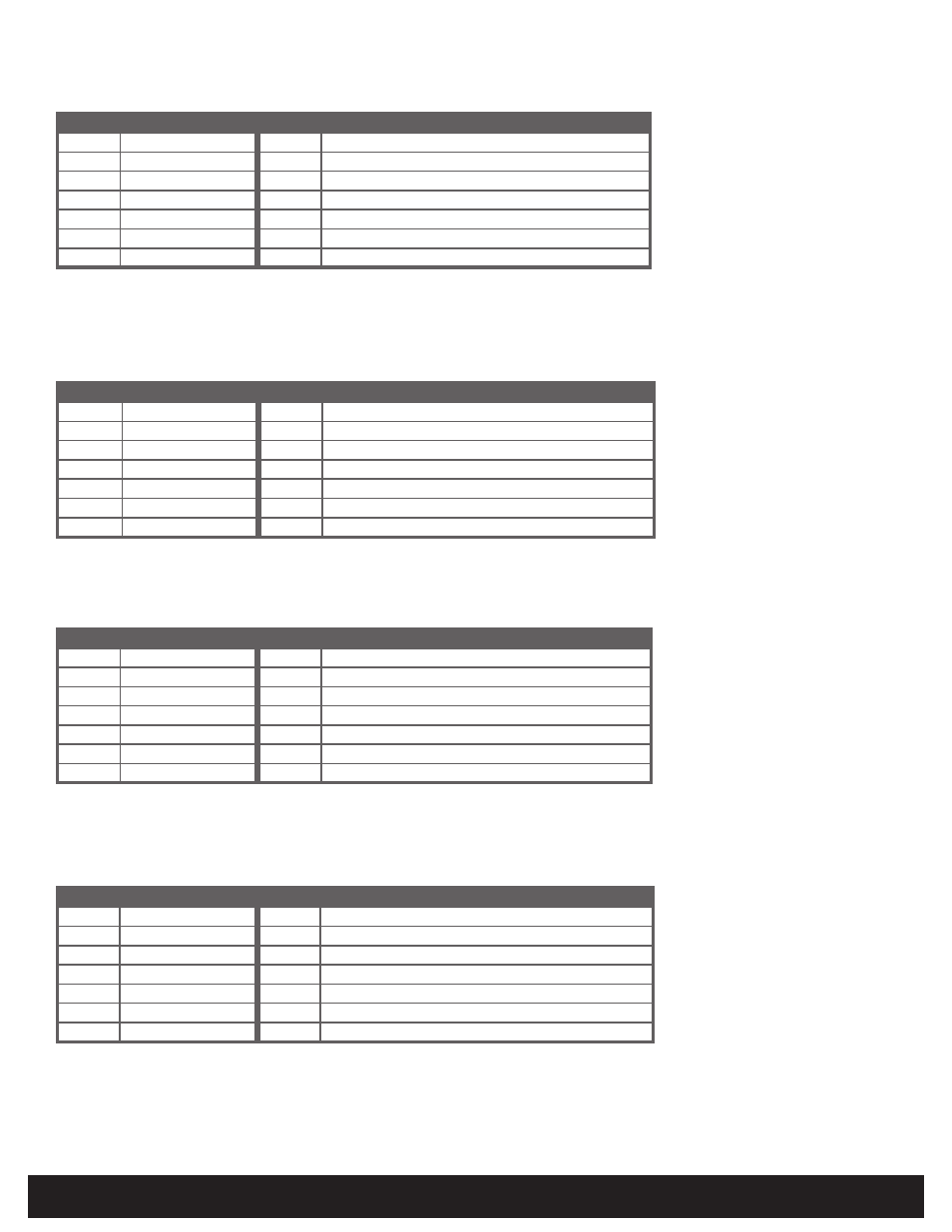
À bornier
Description
À bornier
Description
P1-1
Entrée Beeper
P2-7
**
GPIO1 (RS232-T / RS485-A / HADP-OSDP-A / USB-5V / UART-T)
P1-2
Entrée LED verte (GRN)
P2-6
**
GPIO2 (RS232-R / RS485-B / HADP-OSDP-B / USB-D+ / UART-R)
P1-3
Terre (RTR)
P2-5
*** Sortie à collecteur ouvert
P1-4
+Vcc
P2-4
**** Données Wiegand 1 / Clock
P1-5
* Blindage (BLIND)
P2-3
**** Données Wiegand 0 / Data
P1-6
Entrée LED rouge
P2-2
**
GPIO3 (RS485-Z/USB-D-)
P1-7
Entrée Hold
P2-1
**
GPIO4 (RS485-Y)
*
O fio do dreno pode ser uma linha de “retorno de dados” quando uma alimentação separada é utilizada.
**
Requer Módulo de expansão [ RS232, RS485, USB, UART para UART]. GPIO significa Entrada/saída de uso geral.
***
Saída de tamper. Quando ativada a saída sincroniza com o terra (padrão).
**** Dependente da configuração do leitor. Consulte do HTOG Wiegand e Configurações do Relógio e de Dados para obter mais informações.
Terminal
Descrição
Terminal
Descrição
P1-1
Entrada de bíper
P2-7
**
GPIO1 (RS232-T / RS485-A / HADP-OSDP-A / USB-5V / UART-T)
P1-2
Entrada de LED verde (VRD)
P2-6
**
GPIO2 (RS232-R / RS485-B / HADP-OSDP-B / USB-D+ / UART-R)
P1-3
Terra (RTN)
P2-5
*** Saída do coletor aberta
P1-4
+VDC
P2-4
**** Wiegand-Daten 1/Uhr
P1-5
* Proteção (SHLD)
P2-3
**** Dados Wiegand 0 / Dados
P1-6
Entrada de LED vermelho
P2-2
**
GPIO3 (RS485-Z/USB-D-)
P1-7
Manter entrada
P2-1
**
GPIO4 (RS485-Y)
*
Bei Verwendung eines separaten Netzteils kann der Erdungsdraht als „Datenrücklauf“-Leitung dienen.
**
Erfordert Erweiterungsmodul [RS232, RS485, USB, UART zu UART].
GPIO steht für „General Purpose Input/Output“ (Allgemein verfügbarer Eingang/Ausgang).
***
Manipulationssicherungsausgang. Bei Aktivierung schaltet der Ausgang auf Erdungsleiter um (Standard).
**** Abhängig von Leserkonfiguration. Weitere Informationen siehe HTOG Wiegand- und Clock-and-Data-Konfiguration.
Terminal
Beschreibung
Terminal
Beschreibung
P1-1
Signaltoneingang
P2-7
**
GPIO1 (RS232-T / RS485-A / HADP-OSDP-A / USB-5V / UART-T)
P1-2
Grün (GRN) LED-Eingang
P2-6
**
GPIO2 (RS232-R / RS485-B / HADP-OSDP-B / USB-D+ / UART-R)
P1-3
Erdungsleiter (RTN)
P2-5
*** Open-Collector-Ausgang
P1-4
+VDC
P2-4
**** Wiegand-Daten 1 / Uhr
P1-5
* Abschirmung (SHLD)
P2-3
**** Wiegand-Daten 0 / Daten
P1-6
Eingang rote LED
P2-2
**
GPIO3 (RS485-Z/USB-D-)
P1-7
Hold-Eingang
P2-1
**
GPIO4 (RS485-Y)
*
Il filo di spurgo può essere una linea di “ritorno dati” quando si usa un alimentatore separato.
**
Richiede un modulo di espansione [ RS232, RS485, USB, da UART a UART].
GPIO sta per ingresso/uscita di tipo generale.
***
Uscita tamper. Quando attivata, uscita a negativo (predefinito).
**** Dipende dalla configurazione del lettore.
Per ulteriori informazioni in merito vedere le configurazioni HTOG Wiegand e Clock-and-Data.
Terminale
Descrizione
Terminale
Descrizione
P1-1
Ingresso con cicalino
P2-7
** GPIO1 (RS232-T / RS485-A / HADP-OSDP-A / USB-5V / UART-T)
P1-2
Ingresso LED verde (GRN)
P2-6
** GPIO2 (RS232-R / RS485-B / HADP-OSDP-B / USB-D+ / UART-R)
P1-3
Massa (RTN)
P2-5
*** Uscita collettore aperto
P1-4
+V c.c.
P2-4
**** Wiegand Data 1 / Clock
P1-5
* Schermatura (SHLD)
P2-3
**** Wiegand Data 0 / Clock
P1-6
Ingresso LED rosso
P2-2
** GPIO3 (RS485-Z/USB-D-)
P1-7
Ingresso di tenuta
P2-1
** GPIO4 (RS485-Y)