Sequencer – Spektrum SPM18100 DX18 User Manual
Page 29
29
SPEKTRUM DX18 • TRANSMITTER INSTRUCTION MANUAL
EN
Combo Mixing
Combination Mixing
is available to create
OR mixing. OR mixing
allows you to assign 2
conditions where the
mix will activate if either
condition occurs. You can
also create AND mixing where 2 conditions must occur to activate
the mix.
To program Combination Mixing:
1. Activate a mix.
2. Select Combo Sw. in the Switch Selection. The Combo screen
appears.
3. Select the desired switch and active switch position for Switch
1.The mix is Active when the switch position box is fi lled.
4. Select the Relation (AND, OR)
5. Select the desired switch and active switch position for Switch
2.The mix is Active when the switch position box is fi lled.
6. Press the BACK button to save the Combination Mix.
The Master (left side) names are inputs. For example, “Aileron”
refers to the Aileron Stick. The Slave (right side) name is the name
of the channel receiving the mix command when the Master chan-
nel moves.
Back Mixing
Back Mixing applies a
mix to all related servos
in a wing or tail type. For
example, if you select 2
AIL, 2 FLAP in the Air-
craft Type screen, a mix
to one aileron channel
affects both aileron servos.
The mix response, however, depends on the aileron channel
included in the mix.
A Back Mix also enables you to use fewer mixes to achieve the
desired response, for example adding roll to a split elevator.
1/2 Mixing Values
When adjusting the mix values near center (below 10), 1/2% mix
values are available for fi ne adjustment capability.
IMPORTANT: This function is only available in program mixes and
rudder to aileron/elevator in aircraft model type.
Origin Mixing
Origin Mixing uses true
stick position as the
input for a mix. When
origin mixing is selected,
any other settings to the
master channel will be
ignored and the mix will
be based strictly on stick position and trim position. When Aileron,
Elevator, or Rudder are selected as the master, origin mixing is
available. Once Aileron, Elevator, or Rudder are selected, an N will
appear next to the master channel, where N means normal. Roll
and select the N to change to O for origin mixing. Next, select the
slave channel and set the switch and mix rates as desired.
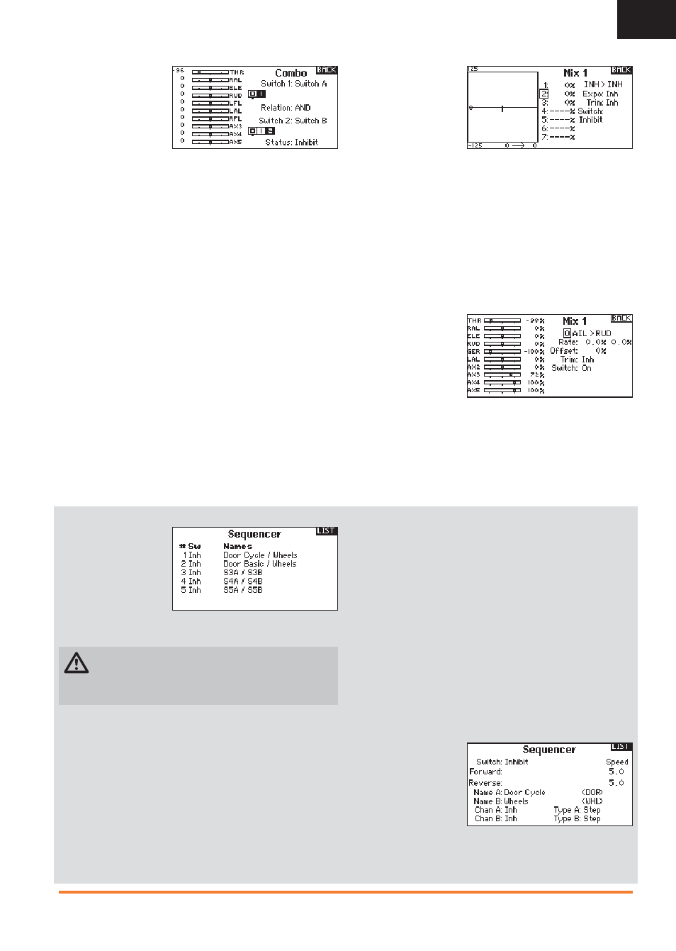
Sequencer
The Sequencer menu
option provides this-
then-that mixing with a
time delay. Five different
sequences (S1 through
S5) are available to
control 2 functions each
(A and B), in 2 timing directions (forward or reverse). Sequences
appear throughout function screens as assignable switches.
CAUTION: Always review the action of a sequence on the
Monitor or X-Plus Monitor screen BEFORE operating the
model to ensure controls act as desired. Failure to do so could
cause a crash, resulting in property damage and or injury.
You can program multiple functions to sequentially activate in
response to an assigned switch. For example, an assigned Gear
switch can open gear doors, lower the gear, then close the doors.
In reverse, gear doors open, the gear retracts and the gear doors
close.
You can assign each Sequencer function to a switch in most
Function screens such as Flight Mode, Dual Rate, Mixing, Throttle
Curve, Pitch Curve, etc.
You can assign several functions to a sequence to decrease
the number of controls you need to touch during complex fl ight
transitions—for example, applying your assigned dual rates and
exponential when the landing gear deploys and the fl ight mode
changes.
If you select an S-Number-A sequence (e.g. S3A), the sequence
operates as a timed 5-position switch. An S-Number-B sequence
operates as a timed 3-position switch. The 5 positions correspond
to the sequencer values shown on the time delay graph in the
second Sequencer screen. In a function screen, highlight each
point (0–4) and select the switch position desired for a function to
be active.
When S1B (or another sequence-number-B) is selected as a
switch in a function, the sequence will operate as a timed 3-posi-
tion switch. The 3 positions act as ‘kick points’ of the movement
at fi xed percentages (equal thirds) of the sequencer output. In a
function screen, highlight each point (0–2) and select the switch
position desired for a function to be active.
Sequencer Set Up
1. In the fi rst Sequencer screen, select 1 of the 5 available
sequences.
2. In the second
Sequencer screen,
assign a switch to
the sequence. We
recommend using a
2-position switch.
Tip: If you need to
use a 3-position switch, you must assign one direction to two
adjacent switch positions—e.g., 0 and 1. Assign the opposite
direction to the third switch position.