Swiftech H20 8500 User Manual
Page 2
Rouchon Industries, Inc., dbA Swiftech – 1703 E. 28
th
St, signal Hill, CA 90755, USA – T (562) 595-8009 – F (562) 595-8769 – All content
Copyright Swiftech 2002 – Last edited Dec 12, 2002 – Subject to revision without notice
- 2 -
4.
MCK525 Pump and Fill & Bleed tray installation
Simply insert the tray as you would a CD Rom drive,
preferably in the uppermost 5 ¼” drive bay. If there is not
enough clearance with the top of the case, then install the
tray in the second highest drive bay. Align the extremity of
the fill and bleed tubes so that they will fit right behind the
drive bay covers. Use the provided screws to attach the tray
to the case. If your case uses drive rails, they will install on
this tray the same way they would on a CR Rom drive.
5. MCR80-F Radiator installation
The assembly fits into any exhaust opening designed to receive a 80mm
case fan. Depending on the case design, the assembly will either fit
straight up (inlet and outlet up), or may need to be rotated 90 as shown
in the example to the left. Depending on the orientation of the radiator, it
is easier to clamp the tubing to the inlet and outlet before fastening the
radiator to the case. Follow the separate installation guide provided in the
MCR80-F box to fasten the radiator to the case.
6.
Pump Relay Switch Installation:
Find a suitable placement to drill a hole for the pump’s A/C socket.
Leave sufficient room under or above the hole to install the pump relay
switch circuit board. A ¼” minimum clearance will be required between
the circuit board and the edge of the hole.
Make a 1.25” (32mm) diameter hole in the case, using a 1 ¼” Bi-Metal
hole saw. Deburr the edges of the hole with sand paper.
Position and center the mounting plate over the hole as a template to
mark the locations of the plate’s mounting screws. Drill 2 holes of .125”
diameter for the mounting screws. Install the mounting plate using the
screws provided with your kit.
Insert the A/C socket inside the mounting plate.
Pump’s relay switc h c ircuit board
A/C Socket
1
.2
5
"
H
o
le
Sp
a
c
in
g
N\O
+
_
0
.2
5
"
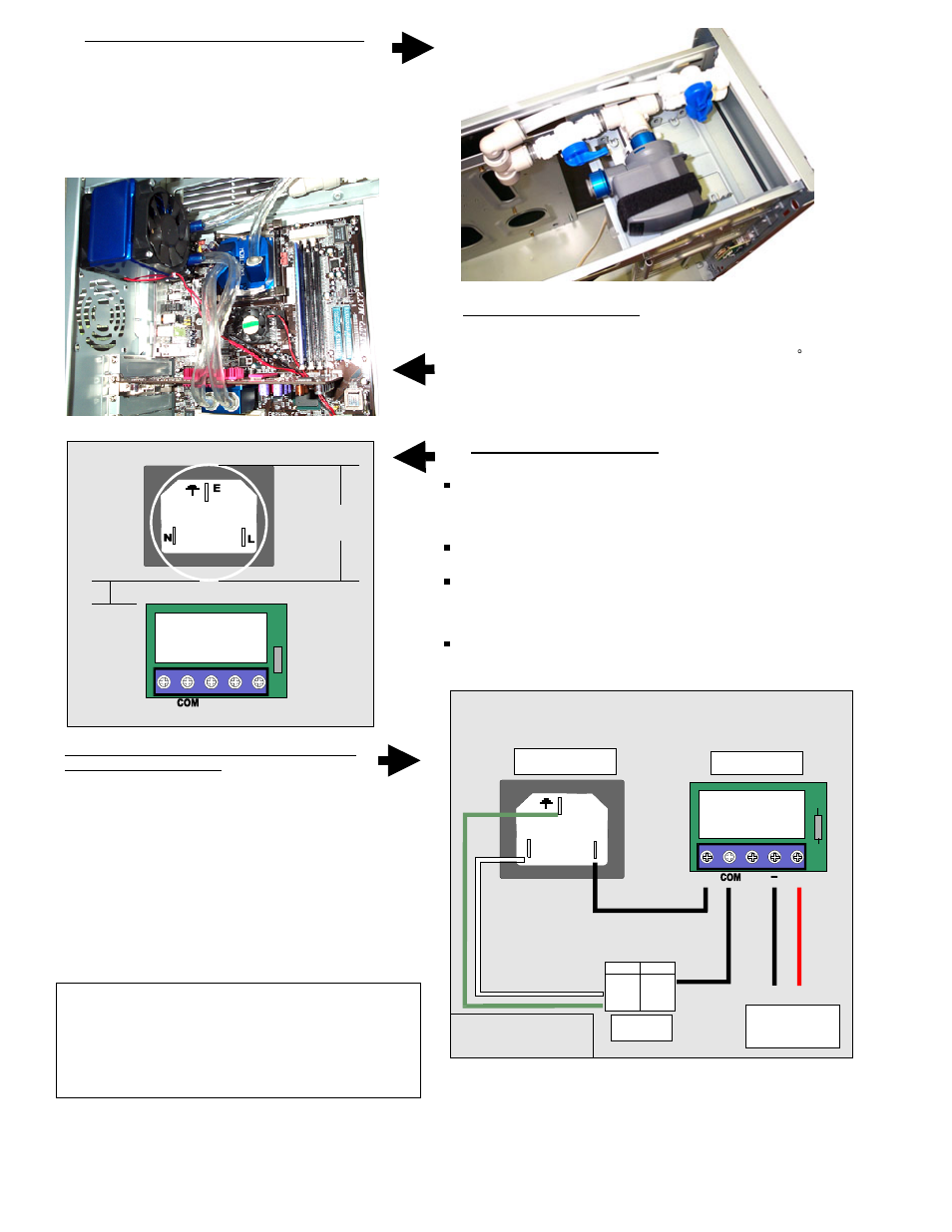
Proceed with electrical connections as described
in the diagram to the right.
For normal operations, connect:
1.
Black L wire from A/C socket to N\O (normally
opened) position on switch
2.
Black wire (brown for Europe) from pump to COM
position on switch
3.
White wire (blue for Europe) to N position on A/C
socket
4.
Green Wire (yellow for Europe) to Ground on A/C
socket
5.
4 pins Molex connector will connect to
computer power supply once installed.
For fill & bleed operations,
TEMPORARILY
connect the L
wire from the A/C socket to the N\C (normally closed)
position on the relay switch. This bypasses the switch,
allowing the pump to run as soon as you plug it into an A/C
outlet. Do not forget to reconnect to N\O once done, or the
pump will shut off when you turn the computer on, instead
of running.
E
N
L
Ground +12v
Relay switch connection diagram
N\O
+
A/C Socket
Pump
Computer
Power Sup ply
Relay switch
US Europe
Black Brown
White Blue
Green Yellow
WARNING! Always disconnect
from A/C power source while
working with electrical devices.
N\C