D table 4-2 d, Able 4-2, and table 4-3 li – Allied Telesis AT-8324 User Manual
Page 69
AT-8316F and AT-8324 Installation Guide
69
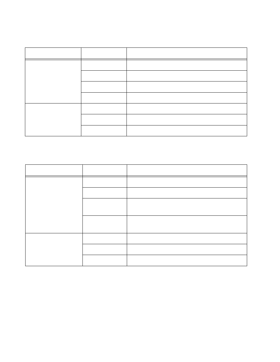
Table 4-3 describes the LEDs on the optional expansion modules.
Table 4-2 Switch Port LED Status
LED
State
Description
L/A (Link/Activity)
Solid Green
This indicates a 100 Mbps link.
Flashing Green
This indicates 100 Mbps activity.
Solid Amber
This indicates a 10 Mbps link. (10/100 ports only)
Flashing Amber
This indicates 10 Mbps activity. (10/100 ports only)
D/C (Duplex/Collision)
Solid Green
The port is operating at full duplex.
Solid Amber
The port is operating at half duplex.
Flashing Amber
Collisions are occurring on the line.
Table 4-3 Expansion Module Port LED Status
LED
State
Description
L/A (Link/Activity)
Solid Green
This indicates a 100 Mbps link.
Flashing Green
This indicates 100 Mbps activity.
Solid Amber
This indicates a 10 Mbps link (AT-A18 module
only).
Flashing Amber
This indicates 10 Mbps activity (AT-A18 module
only).
D/C (Duplex/Collision)
Solid Green
The port is operating at full-duplex.
Solid Amber
The port is operating at half-duplex.
Flashing Amber
Collisions are occurring on the line.