R.p.s input connector – Allied Telesis AT-8324 User Manual
Page 23
AT-8316F and AT-8324 Installation Guide
23
R.P.S Input Connector
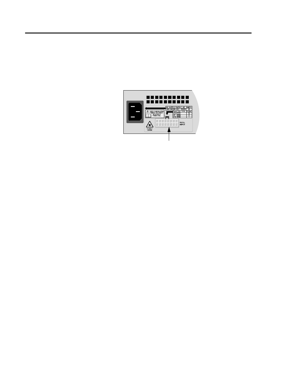
On the back panel of the Ethernet switch is a connector labelled
R.P.S. Input (shown in Figure 1-11). This connector is used to connect
the switch to a redundant power supply (RPS) unit. The RPS shares
the load of powering the switch with the standard power supply that
comes with the Ethernet switch. If one power supply fails, the
remaining unit provides all power to the switch, thus protecting the
switch from a system failure.
Figure 1-11 R.P.S Input Connector
Allied Telesyn offers the AT-RPS8000 redundant power supply
system for the AT-8316F and AT-8324 switches. The RPS system
comes with one redundant power module pre-installed that can
support one Ethernet switch. The AT-RPS8000 unit has three
expansion slots for three additional redundant power modules, each
of which can support an additional switch. Contact your Allied
Telesyn representative for more information about the AT-RPS8000
redundant power supply unit.
R.P.S Input Connector