Slave switch master switch port is-a port is-a – Allied Telesis AT-8324 User Manual
Page 47
AT-8316F and AT-8324 Installation Guide
47
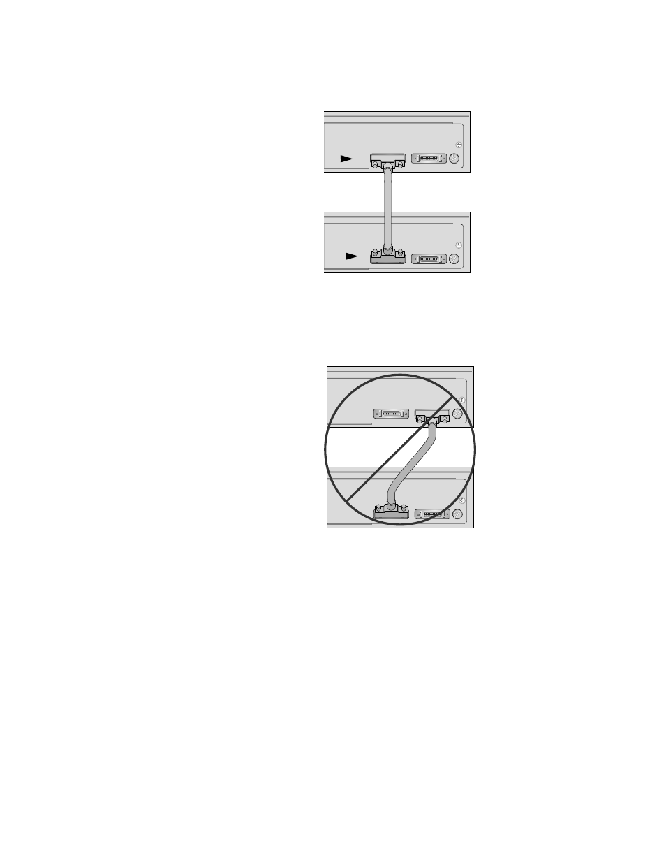
Figure 3-5 illustrates a stack of two switches connected with
one AT-CABLE-4 cable between Port IS-A on the master switch
and Port IS-A on the slave switch.
Figure 3-5 Stack of Two Switches with One AT-Cable-4 Cable
Figure 3-6 illustrates an invalid cabling configuration for a
stack of two switches.
Figure 3-6 Invalid Cabling Configuration for a Stack of Two Switches
IS-A
IS-B
STACK ID
2
IS-A
IS-B
STACK ID
0
1
Slave switch
Master switch
Port IS-A
Port IS-A
IS-A
IS-B
STACK ID
0
IS-A
IS-B
STACK ID
0
1
2
This manual is related to the following products: