Powering on a stack – Allied Telesis AT-8324 User Manual
Page 57
AT-8316F and AT-8324 Installation Guide
57
Powering On a Stack
To power on an Ethernet stack, perform the following procedure:
1. Apply AC power to each slave and master switch in the stack by
plugging a power cord into the AC power connector on the back
panel of the switch (shown in Figure 3-1) and plugging the other
end into a wall outlet.
To simplify the process, you can connect all of the switches,
both master and slaves, to the same power circuit, such as a
power strip, and so be able to apply power to all of the
switches at the same time. If you power ON the switches
individually, you should apply power to the slave switches
first, and then the master switch.
Caution
The power cord is used as a disconnect device. To de-energize
equipment, disconnect the power cord.
"10
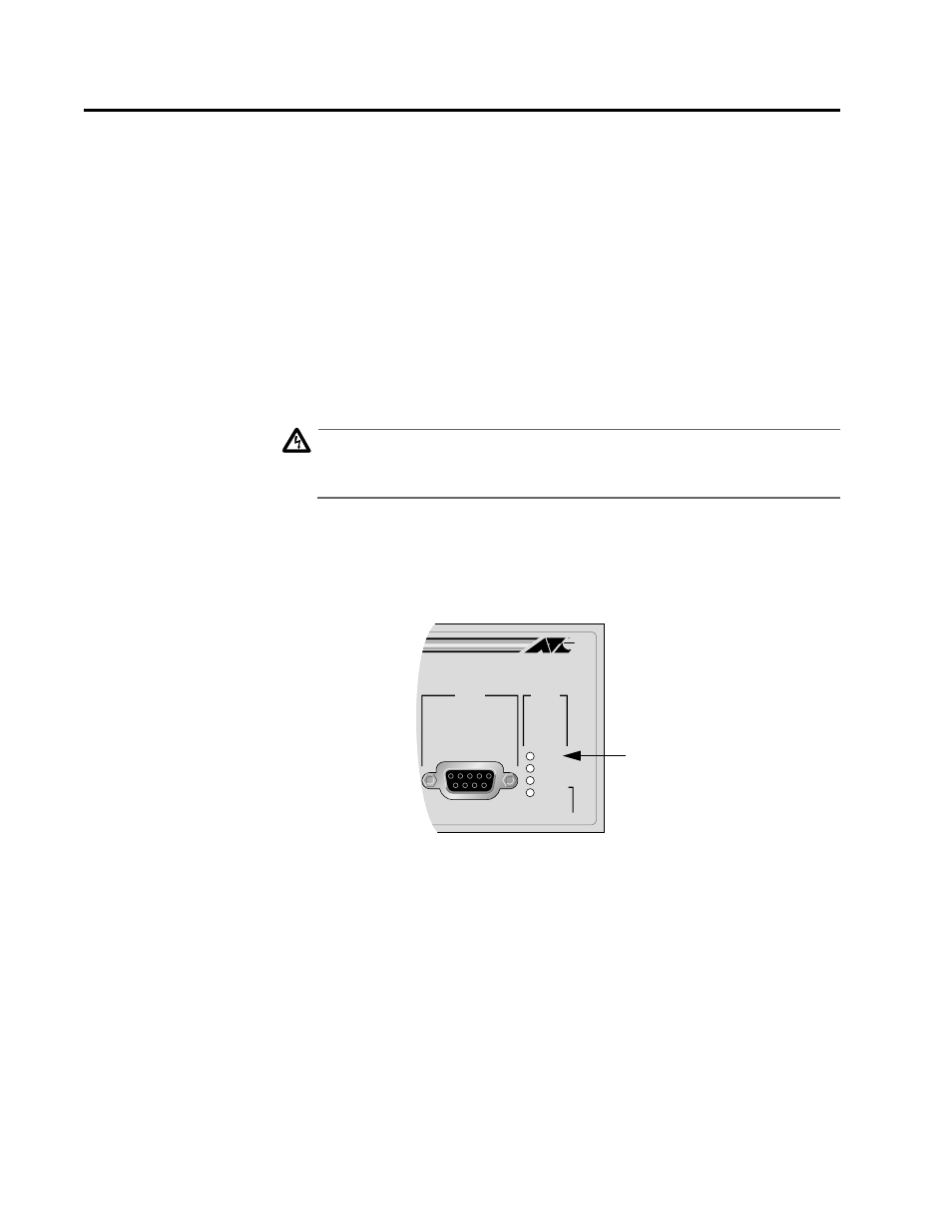
As power is applied to a switch, the Fault LED (shown in Figure
3-14) flashes as a series of internal self tests are performed and
as the hardware is configured. Wait for the Fault LED to stop
flashing and remain OFF.
Figure 3-14 Fault LED
For further information on the switch LEDs, refer to the section
Switch LEDs on page 1-16.
2. Wait while the master switch performs the topology discovery
process. The master switch performs the process in order to
determine the number and types of switches that are in the stack.
During the discovery process, which takes less than one minute to
complete, the port LEDs on each switch will flash in sequence, the
slave switches first and the master switch last.
STATUS
RESET
FAULT
MASTER
RPS
PWR
RS-232
TERMINAL PORT
Fault LED