Card guide – Allied Telesis AT-8324 User Manual
Page 61
AT-8316F and AT-8324 Installation Guide
61
For example, if you install an AT-A17 in slot B of an AT-8324
switch while leaving slot A empty, the switch will assign the
port numbers 25 and 26 to the ports on the module. If you
later install another AT-A17 in slot A, the switch will
automatically reallocate port numbers 25 and 26 to the new
module in slot A and assign the port numbers 27 and 28 to the
module in slot B. If the module in slot B had been a member of
a VLAN, you would be required to reconfigure the VLAN to
reflect the change to its port numbers.
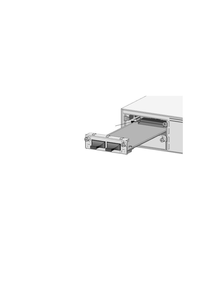
3. Remove the expansion module from the packing material.
4. Slide the expansion module into the empty slot making sure the
board is aligned properly with the card guides. Refer to Figure
3-16.
Figure 3-16 Installing an Expansion Module
5. Secure the expansion module to the switch by tightening the
captive screws.
6. Connect the cabling to the ports on the expansion module.
A
B
AT-A17
100BASE-FX/S
C
RX
TX
RX
TX
LINK
ACTIVITY
FULL DUP
HALF DUP
COL
LINK
ACTIVITY
FULL DUP
HALF DUP
COL
1
2
Card Guide