Installing the switch 50 – Allied Telesis AT-8324 User Manual
Page 50
Installing the Switch
50
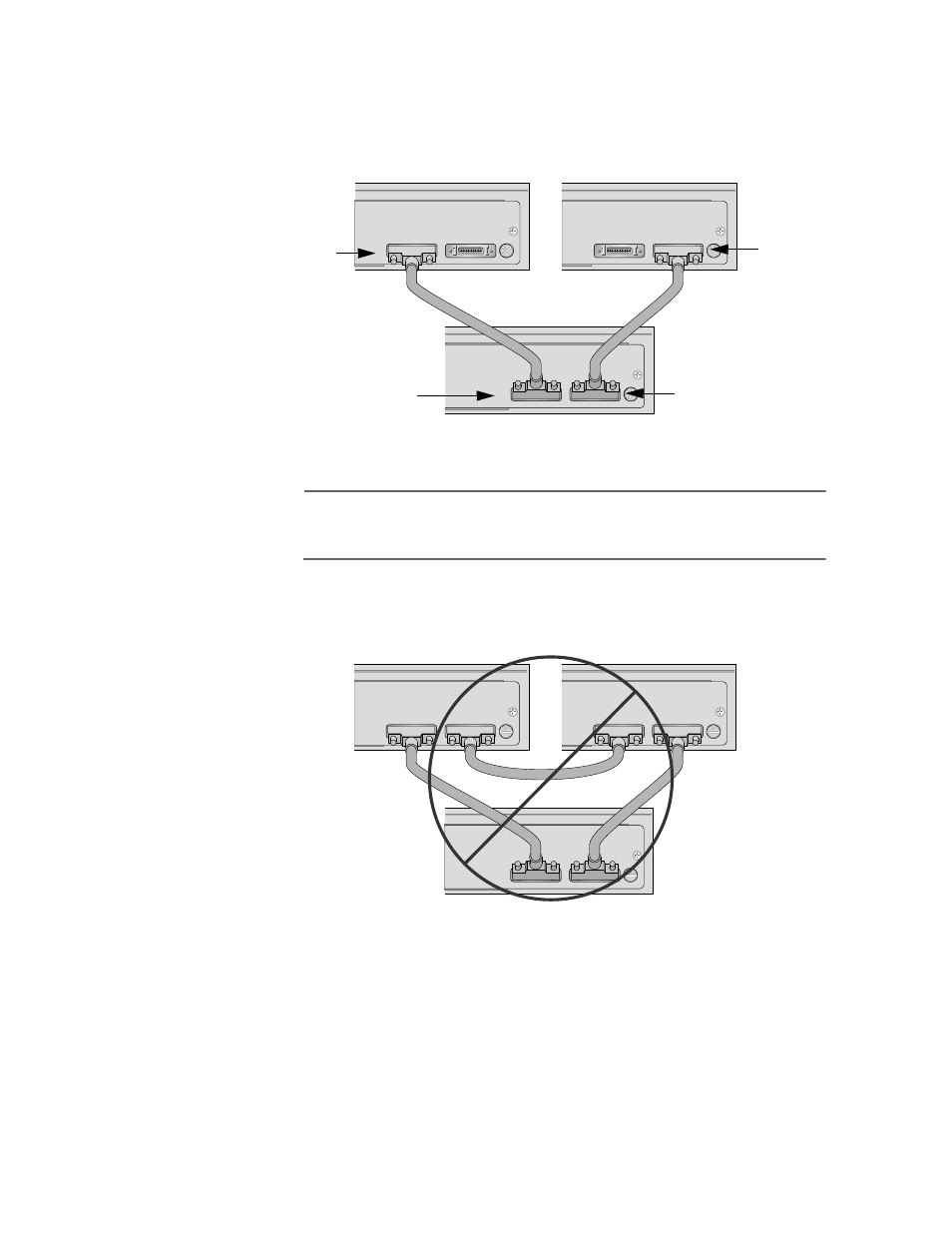
6. Connect one AT-CABLE-4 cable between the IS-A ports on the
master switch and a slave switch, and another AT-CABLE-4 cable
between the IS-B ports on the master switch and the other slave
switch. Refer to Figure 3-8.
Figure 3-8 Valid Cabling Configuration for a Stack of Three Switches
Note
A stack of three switches can have only one cable between the
switches.
Figure 3-9 illustrates an invalid cabling configuration for a
stack of three switches.
Figure 3-9 Invalid Cabling Configurations for a Stack of Three Switches
IS-A
IS-B
STACK ID
0
IS-A
IS-B
STACK ID
0
IS-A
IS-B
STACK ID
0
1
2
3
Master switch
Slave
Port IS-B
Port IS-B
Port IS-A
Port IS-A
Slave
switch
switch
IS-A
IS-B
STACK ID
0
IS-A
IS-B
STACK ID
0
IS-A
IS-B
STACK ID
0
This manual is related to the following products: