Workgroup switch configuration, Figure43 at-3726 switch in department configur, Workgroup switch configuration -3 – Allied Telesis AT-3726 User Manual
Page 39
AT-3714F and AT-3726 Installation Guide
4-3
Workgroup Switch Configuration
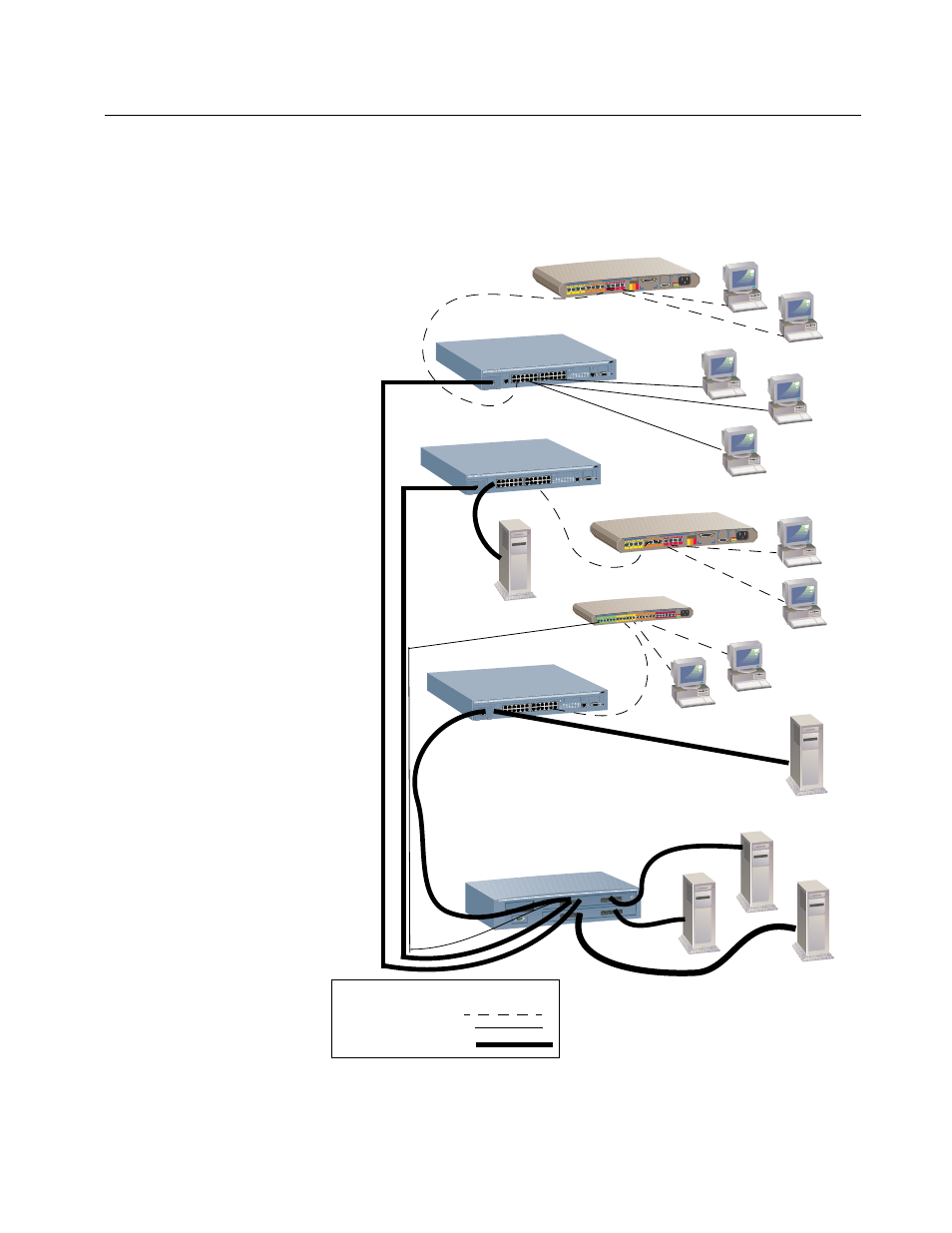
Figure 4-3 and Figure 4-4 show how cascaded AT-3726s and
AT-3714Fs respectively, fit into a large corporate network with a Fast
Ethernet infrastructure. A switch is located on each floor and servers
are centralized in one room.
Figure 4-3 AT-3726 Switch in Department Configuration
AT-3612TR Hub
AT-3726
FORMULA 8200 TX/FX
Server
100TX
Server
Server
Backbone
AT-3624TR Hub
Server
100TX
100TX
10BaseFL (2KM)
Server
AT- 3726
Legend
Shared 10Mbps link
Dedicated 10Mbps link
Dedicated 100Mbps link
PORT B
100BASE-TX
MIRROR PORT
RS-232
TERMINAL PORT
STATUS
10BASE-T
PORT ACTIV
ITY
100 Mbps
100 Mbps
AT-3612TR Hub
PORT B
100BASE-TX
MIRROR PORT
RS-232
TERMINAL PORT
STATUS
10BASE-T
PORT ACTIVITY
PORT B
100BASE-TX
MIRROR PORT
RS-232
TERMINAL PORT
STATUS
10BASE-T
PORT ACTIVITY
AT- 3726