Figure25 connecting the 50-pin female connecto, Attach the three phillips panhead screws that w, Apply power to the unit as follows – Allied Telesis AT-3726 User Manual
Page 29: Mda leds, Table24 media dependent adapter leds, Mda leds -11, Centr e
AT-3714F and AT-3726 Installation Guide
2-11
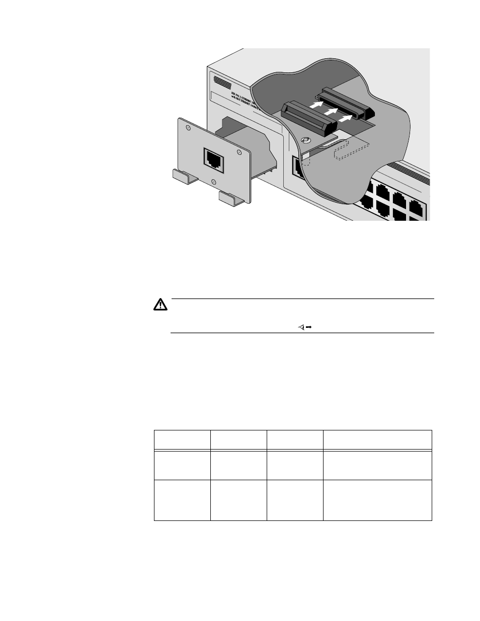
Figure 2-5 Connecting the 50-Pin Female Connector
6. Attach the three Phillips panhead screws that were shipped with the
MDA.
7. Apply power to the unit as follows:
Caution
Power cord is used as a disconnection device. To de-energise equip-
ment disconnect the power cord.
Re-attach the power cord to the unit and plug it in the wall outlet.
Verify that the PWR LED lights green. See Table 2-4.
MDA LEDs
Table 2-4 lists and defines the MDA LEDs. Note that the MDA LEDs
are located on the front panel of the switch under Port Activity.
For troubleshooting techniques, see Chapter 3, “Troubleshooting.”
PORT B
100BASE-TX
10BA
S
1X
3X
5X
7X
9X
11X
2X
AX
4X
6X
8X
3701
100BASE-TX
X
Centr
e
Table 2-4 Media Dependent Adapter LEDs
LED
Color
State
Description
LINK
Green
ON
There is a good physical
link with a device.
ACTIVITY
Green
Flashing
or ON
The Ethernet port is
receiving/transmitting
packets.