Allied Telesis AT-MC602 User Manual
Page 32
Installation
32
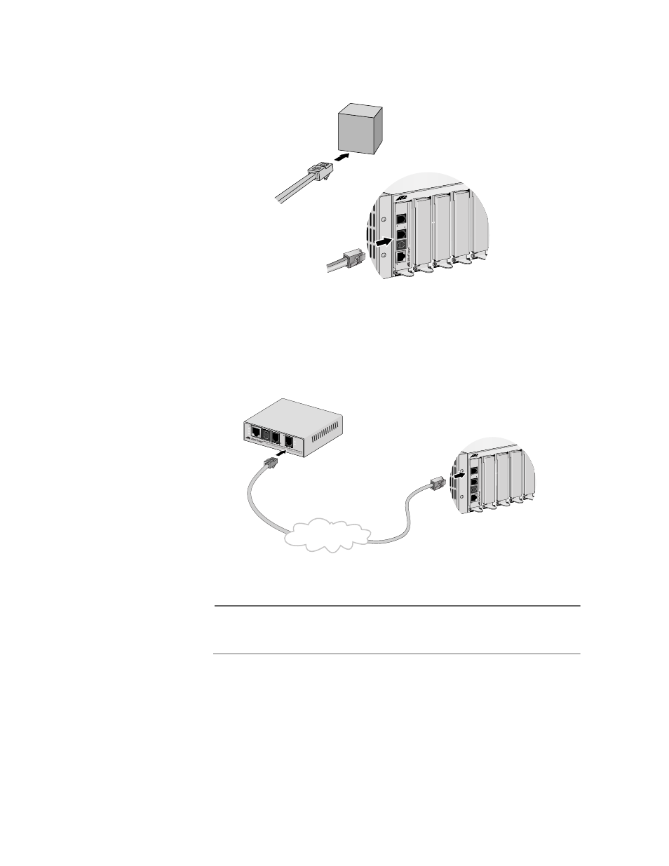
2. Then, connect a telephone line cable from the PSTN port to the
outside telco box, as shown in Figure 16.
Figure 16 PSTN to Telco PBX Line
3. Next, connect a telephone line cable from the VDSL Line port to the
wall/interior telephone line, as shown in Figure 17, so that the
Provider unit can communicate with the Subscriber unit.
Figure 17 VDSL Line to Wall/Interior Phone Line
Note
The procedure for connecting the management cable is described
in ”Cabling Preparations” on page 36.
Telco
PBX
Line
MCR12
LINE
10
Base
T
/
100Base
TX
LINK
AC
T
PWR
ERR
LINK
MGMT
AT
-MC603
VDSL EXTENDED ETHERNET
PSTN
MCR12
LINE
10Base
T
/
10
0Base
TX
LINK
AC
T
PWR
ERR
LINK
MGMT
AT
-MC602
VDSL EXTENDED ETHERNET
PSTN
LINE
10BaseT/
100BaseT
X
PSTN
LINK
ACT
PWR
ERR
LINK
MGMT
AT-MC601
VDSL EXTENDED ETHERNET
Wall/Interior Phone Line