Cabling the provider unit – Allied Telesis AT-MC602 User Manual
Page 31
AT-MC601, AT-MC602 Installation and User’s Guide (For Use with AT-MCR12 Only)
31
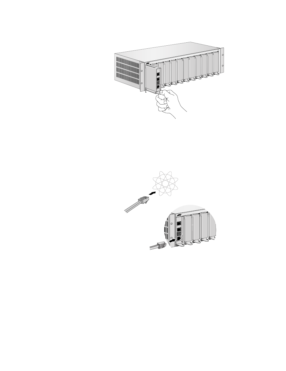
2. Then, set the slider in the chassis, as shown in Figure 14.
Figure 14 Rack Mount - Set in Rack
Cabling the
Provider Unit
To cable the Provider unit, perform the following steps:
1. First, connect the Ethernet cable from the Ethernet port to the Service
Provider box in your wiring closet, as shown in Figure 15.
Figure 15 Ethernet to Internet Service Provider
POWE
R
MCR12
LINE
1
0
Base
T
/
10
0
B
a
s
eT
X
PSTN
LINK
ACT
PWR
ERR
LINK
MGMT
A
T
-MC601
VDSL EXTENDED ETHERNET
MCR12
LINE
10
Base
T
/
10
0Base
TX
LINK
AC
T
PWR
ERR
LINK
MGMT
AT
-MC603
VDSL EXTENDED ETHERNET
PSTN
Internet
Service
Provider
This manual is related to the following products:
See also other documents in the category Allied Telesis Computer hardware:
- AT-GS908M (54 pages)
- AT-x230-10GP (80 pages)
- AT-GS950/48PS (64 pages)
- AT-GS950/10PS (386 pages)
- AT-GS950/16PS (386 pages)
- AT-GS950/48PS (386 pages)
- AT-9000 Series (258 pages)
- AT-9000 Series (1480 pages)
- IE200 Series (70 pages)
- AT-GS950/48 (60 pages)
- AT-GS950/48 (410 pages)
- AT-GS950/8 (52 pages)
- AT-GS950/48 (378 pages)
- SwitchBlade x8106 (322 pages)
- SwitchBlade x8112 (322 pages)
- SwitchBlade x8106 (240 pages)
- SwitchBlade x8112 (240 pages)
- AT-TQ Series (172 pages)
- AlliedWare Plus Operating System Version 5.4.4C (x310-26FT,x310-26FP,x310-50FT,x310-50FP) (2220 pages)
- FS970M Series (106 pages)
- 8100L Series (116 pages)
- 8100S Series (140 pages)
- x310 Series (116 pages)
- x310 Series (120 pages)
- AT-GS950/24 (404 pages)
- AT-GS950/24 (366 pages)
- AT-GS950/16 (44 pages)
- AT-GS950/16 (404 pages)
- AT-GS950/16 (364 pages)
- AT-GS950/8 (364 pages)
- AT-GS950/8 (52 pages)
- AT-GS950/8 (404 pages)
- AT-8100 Series (330 pages)
- AT-8100 Series (1962 pages)
- AT-FS970M Series (330 pages)
- AT-FS970M Series (1938 pages)
- SwitchBlade x3112 (294 pages)
- SwitchBlade x3106 (288 pages)
- SwitchBlade x3106 (260 pages)
- SwitchBlade x3112 (222 pages)
- AT-S95 CLI (AT-8000GS Series) (397 pages)
- AT-S94 CLI (AT-8000S Series) (402 pages)
- AT-IMC1000T/SFP (23 pages)
- AT-IMC1000TP/SFP (24 pages)
- AT-SBx3106WMB (44 pages)