Mount the grounding stud, Fastening the plywood mounting surface to a wall – Allied Telesis AT-iMG6x6MOD Electronics Unit User Manual
Page 21
AT-iMG646MOD Installation Guide
Chapter 4: Installing the Gateway Indoors
21
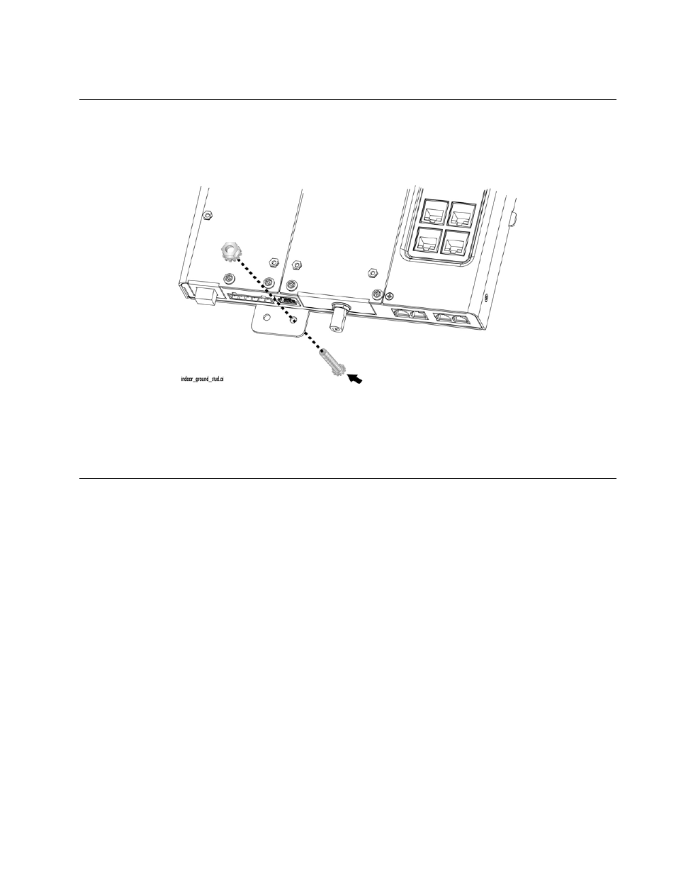
Mount the Grounding Stud
1. Put the included #8-32 x 0.5 in. SEMS screw through the right chassis grounding hole in the chassis, as
shown in Figure 13
2. Secure the screw with a #8-32 Kepnut (not provided), as shown in Figure 13..
Figure 13. Mounting the Grounding Assembly on the Right Mounting Hole
(Note: Instead of the #8-32 Kepnut, you can also use a #8 nut with a lock washer.)
Fastening the Plywood Mounting Surface to a Wall
For an indoor installation, the AT-iMG646MOD series intelligent Multiservice Gateway must be mounted on
a plywood surface that complies with the following specifications:
Recommended minimum size of 12 in. by 12 in. (31 cm by 31 cm)
Recommended minimum thickness of 0.5 in. (1.2 cm)
Rated for indoor use. Medium density fiberboard (MDF) is not recommended.
To fasten the plywood to the wall, perform the following procedure:
1. Select a reasonably flat wall location
2. Using a 3/16 in. (4.5 mm) wood or metal drill bit, drill a hole through each corner of the plywood (only),
approximately 1 in. (2.5 cm) from the edge.
3. Using the plywood as a template, mark the location for the holes on the wall.
4. Using a 3/16 in. (4.5 cm) of the appropriate type drill bit, drill the four holes in the wall at least 1in. (2.5
cm) deep.